


Philips Semiconductors ISP1301 USB OTG Transceiver Eval Kit User’s Guide
UM10028_1 © Koninklijke Philips Electronics N.V. 2003. All rights reserved.
User’s Guide Rev. 1.0—February 2003 5 of 18
1. Introduction
The ISP1301 is a Universal Serial Bus (USB) On-The-Go (OTG) transceiver device that is fully compliant with
Universal Serial Bus Specification Rev. 2.0 and On-The-Go Supplement to the USB 2.0 Specification Rev. 1.0. It integrates a
USB full-speed and low-speed transceiver, and other analog components to fully support OTG functionality.
The ISP1301 is ideal for use in portable electronics devices, such as mobile phones, personal digital assistants
(PDAs), digital still cameras, and digital audio players. The ISP1301 acts as a physical layer to interface with any USB
OTG Controller.
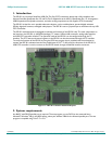
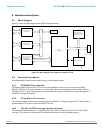
The ISP1301 evaluation board is designed to evaluate the functions of the ISP1301 chip. The main components on
the board are: the ISP1301 (in HVQFN24 package), I
2
C master, USB mini-AB connector, analog audio interface,
and USB OTG controller interface. The operation mode of the ISP1301 can be configured through the I
2
C
interface. The OTG status and control registers in the ISP1301 can also be accessed through the I
2
C interface.
To verify the functions of the ISP1301 by using the DOS test program that is provided with the evaluation kit,
connect the ISP1301 evaluation board to the parallel port of a PC. To fully verify the functions of the ISP1301, a
USB OTG controller is used to connect to the ISP1301 board through the defined interface connector.
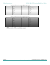
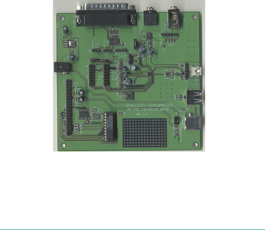
Figure 1-1: ISP1301 evaluation board PCB layout
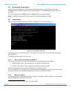
2. System requirements
An x86 PC with DB-25 parallel port is required. The test program runs on DOS (or the command line in
Microsoft
®
Windows
®
98). In the BIOS setting, select port address 378H for the onboard parallel port. The test
program is compiled using Turbo
®
C++ 3.0.