


Philips Semiconductors ISP1301 USB OTG Transceiver Eval Kit User’s Guide
UM10028_1 © Koninklijke Philips Electronics N.V. 2003. All rights reserved.
User’s Guide Rev. 1.0—February 2003 8 of 18
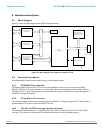
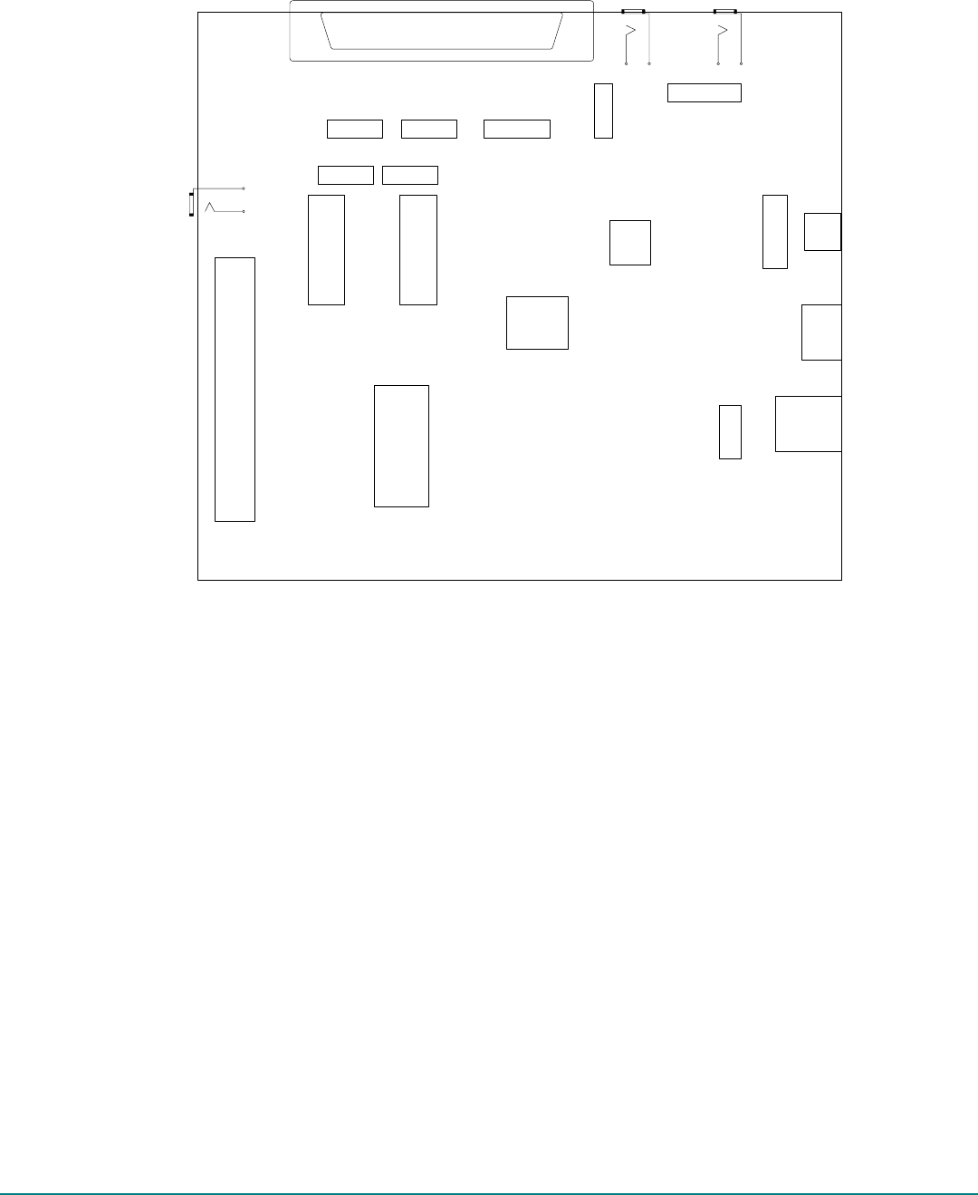
J13
U1
J9
J3
J1
J4
J10
J8
U4
J11
J6 J7
J
5
J
2
J12
JP6
JP4JP3
JP1
JP5 JP2
ISP1301 EVALUATION BOARD
REV 1.0
SW1
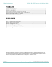
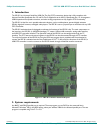
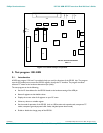
Figure 4-1: Location of major components
5. Test program 1301.EXE
5.1. Introduction
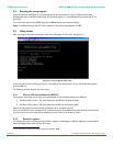
A DOS test program “1301.exe” is provided to help you verify the functions of the ISP1301 chip. The program
uses the PC parallel port to access the ISP1301 registers through the I
2
C interface. The program simulates
software I
2
C master at the hardware abstraction layer (HAL).
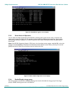
The test program can do the following:
• Set the I
2
C slave address for the ISP1301 based on the hardware setting of the ADR pin
• Reset all registers to their default values
• Display the current value of all registers on your PC screen
• Write any value to a writable register
• Set the mode of operation of the ISP1301 (such as, USB function and suspend mode, transparent I
2
C
mode, transparent general-purpose buffer mode, and global power-down mode)
• Enable or disable the charge pump of the ISP1301.