


Philips Semiconductors ISP1301 USB OTG Transceiver Eval Kit User’s Guide
UM10028_1 © Koninklijke Philips Electronics N.V. 2003. All rights reserved.
User’s Guide Rev. 1.0—February 2003 4 of 18
TABLES
Table 3-1: +5.0 V power selection.......................................................................................................................................................................... 6
Table 3-2: V
BAT
and V
IO
selection.............................................................................................................................................................................. 6
Table 3-3: I
2
C master selection................................................................................................................................................................................ 6
Table 7-1: DB-25 PC parallel port connector (J10) pin assignment..............................................................................................................13
Table 7-2: 8-bit microprocessor-interface 20 x 2 header (J13) pin assignment
[1]
.......................................................................................13
Table 7-3: OTG Controller interface J8 pin assignment..................................................................................................................................14
Table 7-4: OTG Controller interface J3 pin assignment..................................................................................................................................14
Table 9-1: BOM of the ISP1301 evaluation board.............................................................................................................................................17
FIGURES
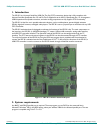
Figure 1-1: ISP1301 evaluation board PCB layout ...............................................................................................................................................5
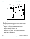
Figure 4-1: Location of major components........................................................................................................................................................... 8
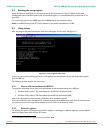
Figure 5-1: Test program main menu..................................................................................................................................................................... 9
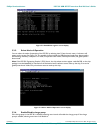
Figure 5-2: List all registers screen display..........................................................................................................................................................10
Figure 5-3: Read/Write register screen display..................................................................................................................................................11
Figure 5-4: Select Mode of Operation screen display.......................................................................................................................................11
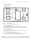
Figure 6-1: Block diagram of the ISP1301 evaluation board............................................................................................................................12
Microsoft and Windows are registered trademarks of Microsoft Corp. Intel is a registered trademark of Intel, Inc.
The names of actual companies and products mentioned herein may be the trademarks of their respective owners.
All other names, products, and trademarks are the property of their respective owners.