Chapter 2 System Component Descriptions 17
17
ST-133 Controller
Electronics: The Model ST-133 is a compact, high performance CCD Camera
Controller for operation with Princeton Instruments cameras. Designed for high speed
and high performance image acquisition, the ST-133 offers data transfer at speeds up to 5
megapixel per second, standard video output for focusing and alignment. A variety of
A/D converters are available to meet different speed and resolution requirements.
In addition to containing the power supply, the controller contains the analog and digital
electronics, scan control and exposure timing hardware, and controller I/O connectors, all
mounted on user-accessible plug-in modules. This highly modularized design gives
flexibility and allows for convenient servicing.
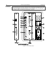
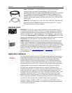
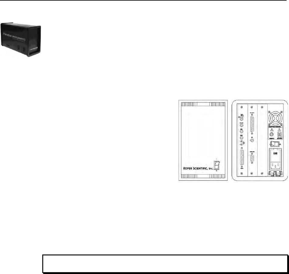
POWER Switch and Indicator: The power
switch location and characteristics depend on
the version of ST-133 Controller that was
shipped with your system. In some versions,
the power switch (when located on the front
panel as shown in Figure 3), has an integral
indicator LED that lights whenever the ST-133
is powered. In other versions, the power switch
is located on the back of the ST-133 and does
not include an indicator LED.
Rear Panel Connectors: There are three
controller board slots. Two are occupied by the
plug-in cards that provide various controller
Figure 2. Power Switch Location
(ST-133A and ST-133B)
functions. The third, covered with a blank panel, is reserved for future development. The left-
most plug-in card is the Analog/Control module. Adjacent to it is the Interface Control
module. Both modules align with top and bottom tracks and mate with a passive backplane
via a 64-pin DIN connector. For proper operation, the location of the modules should not be
changed. Each board is secured by two screws that also ground each module’s front panel.
Removing and inserting boards is described in Chapter 7, pages 80-81.
To minimize the risk of equipment damage, a module should never be removed or
installed when the system is powered.
The Analog/Control Module, which should always be located in the left-most slot,
provides the following functions.
Pixel A/D conversion
Timing and synchronization of readouts
CCD scan control
Temperature control
Exposure control
Video output control
The Interface Control Module, which should always be located in the center slot,
provides the following functions.
TTL in/out Programmable Interface
Communications Control (TAXI or USB 2.0 protocol)
WARNING!


