


2 – General Description
Chassis Controls and LEDs
59096-04 A 2-3
A
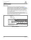
2.1.1.2
Placing the Switch in Maintenance Mode
To place the switch in maintenance mode, do the following:
1. Isolate the switch from the fabric.
2. Press and hold the Maintenance button with a pointed tool for a few seconds
until the Heartbeat LED alone is illuminated. Continue holding the
maintenance button until the Heartbeat LED extinguishes, then release the
button. The Heartbeat LED illuminates continuously while the switch is in
maintenance mode.
To exit maintenance mode and return to normal operation, momentarily press and
release the Maintenance button to reset the switch.
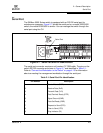
2.1.2
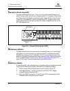
Chassis LEDs
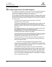
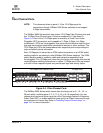
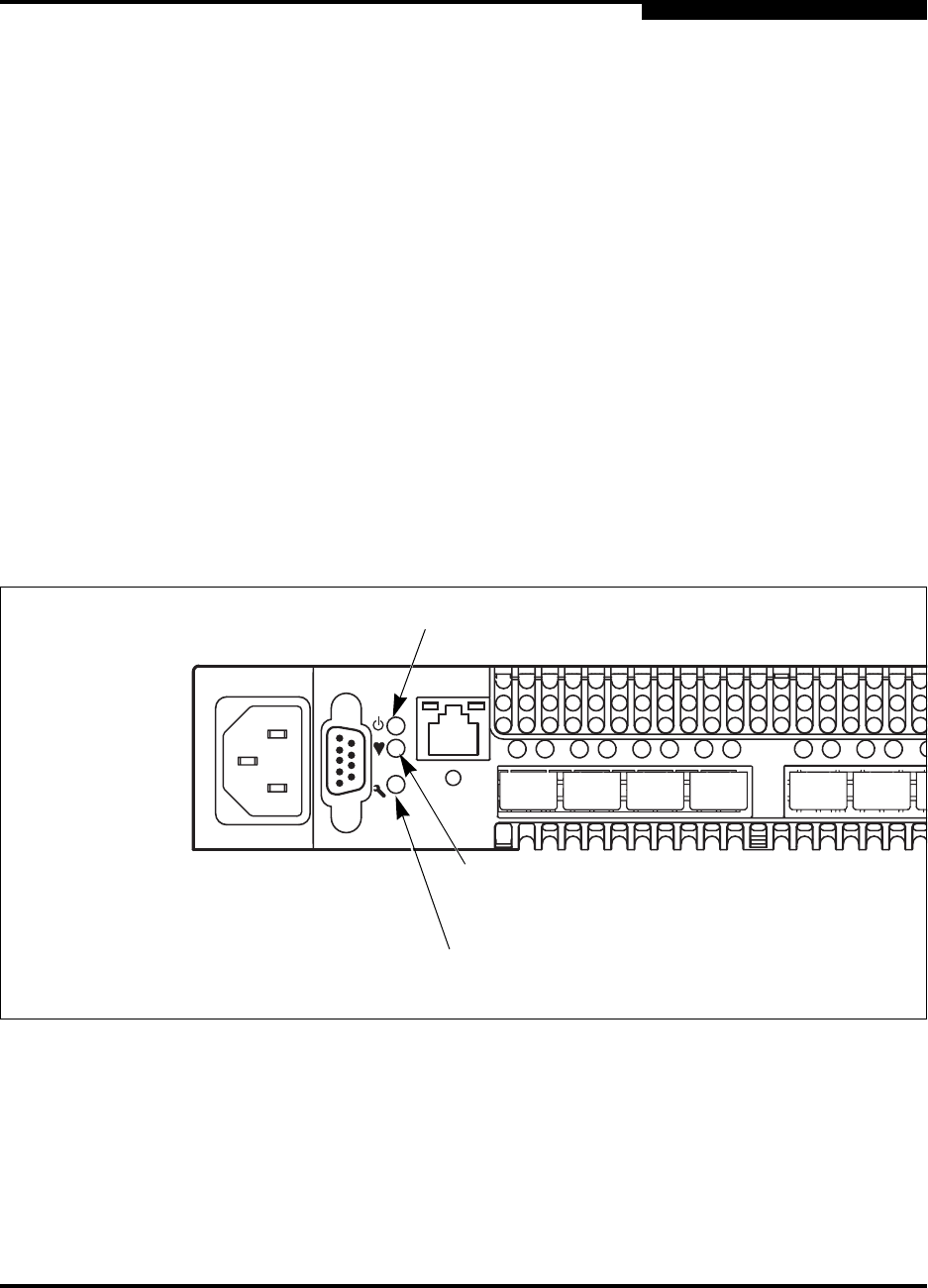
The chassis LEDs provide status information about switch operation. Figure 2-3
identifies the chassis LEDS on a model 5200/5600 switch. The model 5202/5602
switch LED arrangement is the same. Refer to “Port LEDs” on page 2-6 for
information about port LEDs.
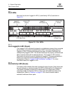
Figure 2-3. Chassis LEDs
L
AL AL AL
ALA
L
A
L
0
1
2
3
4
5
System Fault LED
(Amber)
Heartbeat LED
(Green)
Input Power LED
(Green)