


2 – General Description
Chassis Controls and LEDs
2-4 59096-04 A
S
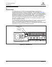
2.1.2.1
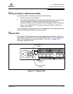
Input Power LED (Green)
The Input Power LED indicates the voltage status at the switch logic circuitry.
During normal operation, this LED illuminates to indicate that the switch logic
circuitry is receiving the proper DC voltages. When the switch is in maintenance
mode, this LED is extinguished.
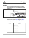
2.1.2.2
Heartbeat LED (Green)
The Heartbeat LED indicates the status of the internal switch processor and the
results of the POST. Following a normal power-up, the Heartbeat LED blinks
about once per second to indicate that the switch passed the POST and that the
internal switch processor is running. In maintenance mode, the Heartbeat LED
illuminates continuously. Refer to “Heartbeat LED Blink Patterns” on page 5-3 for
more information about Heartbeat LED blink patterns.
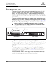
2.1.2.3
System Fault LED (Amber)
The System Fault LED illuminates to indicate a fault exists in the switch firmware
or hardware. Fault conditions include POST errors, over temperature conditions,
and power supply malfunctions. The Heartbeat LED shows a blink code for POST
errors and over temperature conditions. Refer to “Heartbeat LED Blink Patterns”
on page 5-3 for more information about Heartbeat LED blink patterns. On model
5202/5602 switches, the Power Supply Fault LED indicates power supply faults.
Refer to “Power Supply Diagnostics” on page 5-12 for information about power
supply faults.