


5 – Diagnostics/Troubleshooting
Chassis Diagnostics
5-2 59096-04 A
S
5.1.1
Input Power LED Is Extinguished
The Input Power LED illuminates to indicate that the switch logic circuitry is
receiving proper voltages. If the Input Power LED is extinguished, do the
following:
1. Inspect the power cords and connectors. Is the cord unplugged? Is the cord
or connector damaged?
Yes - Make necessary corrections or repairs. If the condition remains,
continue.
No - Continue.
2. Inspect the AC power source. Is the power source delivering the proper
voltage?
Yes - Continue.
No - Make necessary repairs.
For a model 5200/5600 switch, if the condition remains, contact
your authorized maintenance provider.
For a model 5202/5602 switch, if the condition remains, continue.
3. Inspect the power supplies. Are the power supplies fully seated in their
bays?
Yes - Continue. Replace the power supplies.
No - Reinstall the power supplies. If the condition remains, replace the
power supplies.
5.1.2
System Fault LED Is Illuminated
The System Fault LED illuminates to indicate that a fault exists in the switch
firmware or hardware. If the System Fault LED illuminates, do the following:
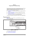
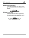
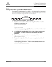
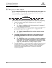
Check the Heartbeat LED for an error blink pattern and take the necessary
actions. Refer to “Heartbeat LED Blink Patterns” on page 5-3.
For a model 5202/5602 switch, check the power supply LEDs and take the
necessary actions. Refer to “Power Supply Diagnostics” on page 5-12.