Installing the Bridge Hardware
23
2.4 Compatible Modbus Devices and Cables
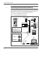
The Bridge connects directly by RJ45 cable to various products shown in Figure 7.
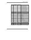
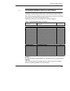
Table 8 below lists other Modbus devices and their cable connections to the Bridge.
Connections are RS–232 unless indicated otherwise.
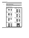
Cable pinout references are to the diagrams in Figure 8 on page 24.
Table 8 Compatible Modbus Devices and Cables
Device
Part Number
Device
Description
Cable Pinout
(Figure 8)
MM–PM10–2xx PanelMate Plus 1000 (RS232) A
MM–PM10–2xx PanelMate Plus 1000 (RS422) B
AS–J478–000 Modbus Modem, Fixed Modem Control C
AS–J478–000 Modbus Modem, Variable Modem Control D
AS–J347–001 184/384 Controller Modbus Interface E
AS–J375–000 Micro 84 Controller Modbus Interface E
AS–P190–xxx P190 Programming Panel E
AS–884A–xxx 884 Controller E
AS–984x–xxx 984A, B, X Controller E
– – PC Serial Port, 9–Pin F
AS–P892–000 ASCII/RIO Interface G
140 CPU 424 xx Quantum Controller, 486 G
140 CPU 534 xx Quantum Controller, 586 G
PC–0984–xxx 984 Controller, 38x/48x/68x/78x Slot Mount G
PC–A984–xxx 984 Controller, Compact G
PC–E984–24x/25x 984 Controller, Compact G
PC–E984–455 984 Controller, 484 Replacement G
PC–M984–xxx Micro–984 Controller G
NW–BM85xxxx BM85 Bridge Multiplexer G
– – Generic Modbus Serial Device, 9–Pin G
110 VPU 192 00 Programmer, Handheld H
AS–A584–xxx 584A, L, M Controller See 584 Note
TSX SCx TSX Controllers, Modbus Interface See TSX Note
584 Note
Use cable AS–W192–XXX with Adapter 110 XCA 204 02, pinouts in Figure 8 cable E.
TSX Note
TSX Controller products offer multiple options for cable connection to the Bridge.
Refer to your product guidebook for more information.


