Starter Kit Instruction Manual Description 13
4.3 DFB and FP Quantum Cascade Lasers
4.3.1 Description
Quantum Cascade Lasers (Q C L ) are unipolar lasers
emitting in the mid-infrared from 4 to 17 microns.
The laser is a ridge of InGaAs a nd AlInAs grown
on InP providing gain and a Fabry-Perot cavity in
order to build the laser oscillation up. Distributed-
Feedback(DFB) Quantum Cascade Lasers are then
obtained by adding a grating, forcing the laser to
emit at the target wavelength.
4.3.2 Geometry of QC lasers
Mountings
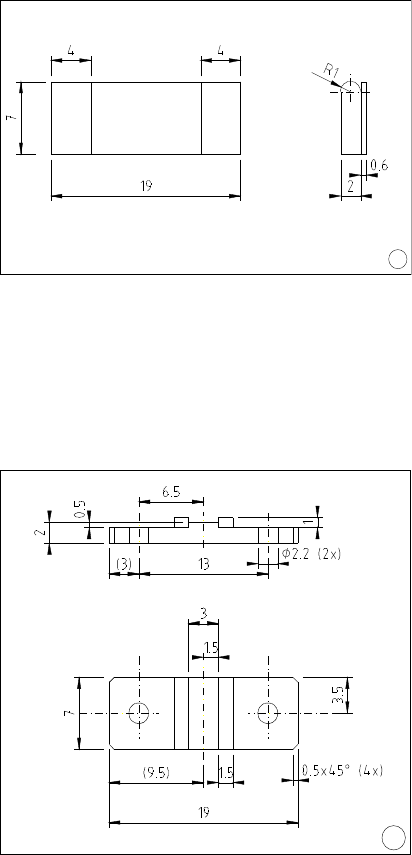
Lasers exist in two different packages:
• ST mounting (1)
• NS mounting (2)
Axes of QC lasers
The vertical direction is the so ca lled growth direc-
tion.
Device are mounted on a copper carrier which
has one or two ceramic pads carrying the bonding
wires. The pads are yellow on top due to a layer of
gold, and white around it and on the sides (colour
of the ceramic). If these pads are placed upwards,
the vertical for the laser is the same as the observer
vertical direction.
If there are two ceramic pads pr e sent, they are
named as follows:
Looking onto the front facet with the laser placed
as described above, the pad left of the laser chip is
called ”DN” (for DOWN), the one on the right of
it ”UP”.
If no c onfiguration is specified,
the ”DN” pad is used.
Never place the laser upside-down, since this will
damage the bonds connecting the pads to the laser
and p ossibly the laser itself!
The laser chips mounted on NS submounts pro-
vided separately from a LLH100 are supplied in a
round plastic box. For removing the laser from it,
please follow the instructions as described in ap-
pendix (appendix 10.2, p.59)
1
Fig.3: ST submount
2
Fig.4: NS submount


