Starter Kit Instruction Manual Use 31
6.3 TCU151 command description
The internal temperature of the LLH100 is driven
by the TCU151 unit.
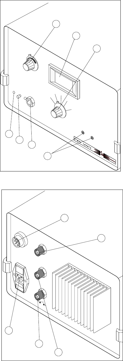
The Temperature Controler front and rear pan-
els are compose d of the following items:
(1) Set Tempera ture 5 turns potentiometer:
Allows to set the internal temperature refer-
ence.
(2) LCD 3 digits display: Used to display ei-
ther the actual sensor or reference tempera-
ture/current.
(3) Switch to select which temperature or cur-
rent signals to display.
(4) Alarm display LED.
(5) Alarm reset switch.
(6) Switch which selects between the internal
and the remote temperature reference.
(7) Setting Current adjustment potentiome-
ters.
(8) Power ON/OFF fuse combined main switch.
(9) To LLH100: Amphenol connector for LLH100
temper ature control.
(10) Interlock BNC connector.
(11) External reference BNC connector.
(12) Monitoring: BNC connector providing
the temperature of the sensor as 10mV/
◦
C
signal.
0
1
U
S
E
O
N
L
Y
W
I
T
H
2
5
0
V
F
U
S
E
S
/
E
M
P
L
OY
E
R
U
N
I
Q
U
E
M
E
N
T
A
V
E
C
D
E
S
F
USI
B
L
E
S
DE
2
5
0
v
1
1
0
−
1
2
0
V
2
2
0
−
2
4
0
V
U
T
P
U
T
M
a
x
:
1
5
V
/
6
A
M
O
N
I
T
O
R
I
N
G
1
0
m
V
/
C
Z
o
u
t
:
2
0
0
o
h
m
E
x
t
e
r
n
a
l
R
e
f
.
1
0
0
m
V
/
C
Z
i
n
:
1
M
o
h
m
I
n
t
e
r
l
o
c
k
i
n
g
9
12
11
10
8
Fig.20: TCU151 temperature controler rear panel
TCU151
T
e
m
p
e
r
a
t
u
r
e
C
o
n
t
r
o
l
l
e
r
A
l
a
r
m
R
e
s
e
t
E
x
t
e
r
n
a
l
I
n
t
e
r
n
a
l
R
e
a
l
I
R
e
a
l
C
S
e
t
t
i
n
g
C
S
e
t
t
i
n
g
+
I
S
e
t
t
i
n
g
−
I
+
−
1
2
3
4
5
6
7
Fig.19: TCU151 temperature controler front panel


