


Starter Kit Instruction Manual Maintenance 46
8.4.2 TCU151 temperature controller
calibration
! WARNING ! Keep in mind that during
the calibration procedure, the instrument is
powered on.
Before beginning
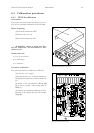
[1] Power off the instrument.
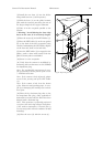
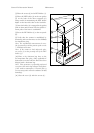
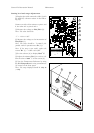
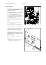
[2] Open the TCU151 top cover (1) to access
the TCU151 main board (2 ).
Material needed
• Voltmeter HP3458A or equiva le nt.
• Voltage source Keithley SMU237 or equiva-
lent.
• Precision resistor 100 Ohm 1% or better.
• Cable: LEMO 6 poles female 6 banana s fe-
male (LEMO connector: LFGG.1B.30 6.CLAD72Z,
LEMO handler GMA.1B.065.DG).
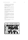
Procedure
+5V/-5V power supply check.
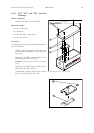
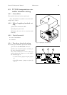
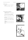
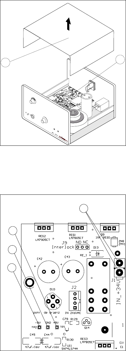
CAUTION ! Do not connect the signal IN-34
V DC (connector J1 (3)).
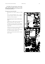
[1] Check the input impedance between +5V/-
5V and GND
note: The values should be:
– TP1 (4) - GND (5): > 5 kΩ.
– TP2 (6) - GND (5): < 4 kΩ.
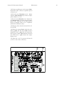
[2] Power on the instrument.
[3] Check the +5V/-5V power supply volt-
age.
Note: The values should be:
– TP1 (4) - GND (5): 4.95 to 5.2 V.
– TP2 (6) - GND (5): 4.95 to 5.2 V.
2
1
T
e
m
p
e
r
a
t
u
r
e
C
o
n
t
r
o
l
l
e
r
A
l
a
r
m
R
e
s
e
t
E
x
t
e
r
n
a
l
I
n
t
e
r
n
a
l
R
e
a
l
I
R
e
a
l
C
Se
t
t
i
n
g
C
S
e
t
t
i
n
g
+
I
S
e
t
t
i
n
g
−
I
+
−
TCU151
Fig.37: Removing the top cover
3
6
5
4
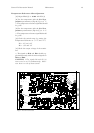
Fig.38: TCU151 main board