


Chapter 6. User Circuitry
6.1. Switches
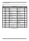
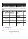
There are four switches located on the CPU board. The function of each switch and its connection are shown in Table 6-1.
Switch Function Microcontroller
RES When pressed; the CPU board microcontroller is reset. RESn
SW1/BOOT* Connects to an IRQ input for user controls.
The switch is also used in conjunction with the RES switch to place
the device in BOOT mode when not using the E8 debugger.
IRQ0n, Pin 39
(Port 1, pin 4)
SW2* Connects to an IRQ line for user controls. IRQ2n , Pin 87
(Port F, pin 0)
SW3* Connects to the ADC trigger/ IRQ3 input via option 0R link R105. IRQ3n, Pin 83
(Port F, pin 3)
Table 6-1: Switch Functions
*Refer to schematic for detailed connectivity information.
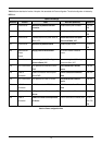
6.2. LEDs
There are six LEDs on the CPU board. The green ‘POWER’ LED lights when the board is powered. The orange BOOT LED indicates the
device is in BOOT mode when lit. The four user LEDs are connected to an IO port and will light when their corresponding port pin is set low.
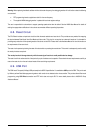
Table 6-2, below, shows the LED pin references and their corresponding microcontroller port pin connections.
LED Reference (As
shown on silkscreen)
Microcontroller Port Pin
function
Microcontroller Pin
Number
Polarity
LED0 Port F1 86 Active Low
LED1 Port F2 85 Active Low
LED2* Port A0 30 via R133 Active Low
LED3 Port G0 101 Active Low
Table 6-2: LED Port
*Refer to schematic for detailed connectivity information.
6.3. Potentiometer
A single turn potentiometer is connected to AN0 of the microcontroller via R42. This may be used to vary the input analog voltage value to
this pin between AVCC and Ground.
6.4. Serial port
The microcontroller programming serial port (SCI2) is connected to the E8 connector by default. SCI0 is connected to the 9-way D-type
connector labelled J8 via a RS232 transceiver.
10