


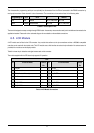
The microcontroller programming serial port can optionally be disconnected from the E8 and connected to the RS232 transceiver by
moving option resistors. Serial channel 0 is then disconnected. The connections to be moved are listed in the following table.
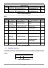
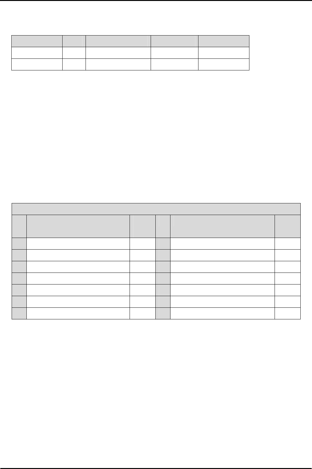
Programming via SCI 2 SCI 0 Fit Remove
E8 E8 RS232 R6, R7, R28, R29 R37, R38
Serial RS232 Disconnected R37, R38 R6, R7, R28, R29
Table 6-3 - Serial Option Links
The board is designed to accept a straight through RS232 cable. A secondary microcontroller serial port is available and connected to the
application headers. Please refer to the schematic diagram for more details on the available connections.
6.5. LCD Module
A LCD module can be fitted to the LCD connector. Any module that conforms to the pin connections and has a KS0066u compatible
controller can be used with the tutorial code. The LCD module uses a 4bit interface to reduce the pin allocation. No contrast control is
provided; this must be set on the display module.
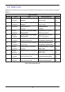
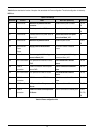
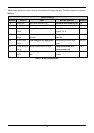
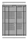
Table 6-4 shows the pin allocation and signal names used on this connector.
The module supplied with the CPU board only supports 5V operation.
LCD
Pin Circuit Net Name Device
Pin
Pin Circuit Net Name Device
Pin
1 Ground - 2 5V Only -
3 No Connection - 4 D0_DLCDRS 111
5 R/W (Wired to Write only) - 6 D1_DLCDE 113
7 No Connection - 8 No connection -
9 No Connection - 10 No connection -
11 D4_DLCDD4 117 12 D5_DLCDD5 118
13 D6_DLCDD6 119 14 D7_DLCDD7 120
Table 6-4 LCD Module Connections
11