


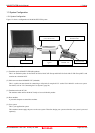

M3062PT2-EPB User’s Manual 1. Outline
REJ10J0868-0200 Rev.2.00 January 16, 2006 Page 18 of 102
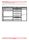
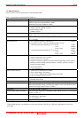
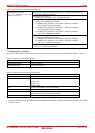
1.4 Specifications
Tables 1.5 and 1.6 list the specifications of the M3062PT2-EPB.
Table 1.5 Specifications of the M3062PT2-EPB (1/2)
Applicable MCU M16C/60 Series M16C/62P Group and M16C/30 Series M16C/30P Group MCUs
Applicable MCU mode Single-chip mode
Memory expansion mode (NORMAL, 4MB)
Microprocessor mode (NORMAL, 4MB)
Maxi. ROM/RAM capacity 1. Internal flash ROM: 516KB
0F000h--0FFFFh, 80000h--FFFFFh
2. Internal RAM: 31KB
00400h--07FFFh
Applicable power supply Vcc1 = Vcc2: 2.7--5.5 V
Vcc1 > Vcc2: Vcc1 = 5.0 ± 0.2 V, 2.7 V ≤ Vcc2 < Vcc1
Maximum operating frequency 3.0 to 5.5 V: 24 MHz (when using a PLL)
2.7 V: 10 MHz
Emulation memory 1. Max. operating frequency of ROM area 10 MHz
2. External area (CS3# -- CS0# area) Minimum 4KB x 4 areas
- Maximum operating frequency (at 5.0 V) 0 wait: 7 MHz
1 wait: 20 MHz
2 wait, 3 wait: 24 MHz
- Maximum operating frequency (at 3.0 V) 0 wait: 6 MHz
1 wait: 17 MHz
2 wait, 3 wait: 24MHz
Basic debugging functions - Download
- Address match break (max. 8 points)
- Software break (max. 64 points)
- Program execution/stop (allows free-run execution supporting software breaks)
- Memory reference/setting (reference/setting C-variables, run-time execution)
- Register reference/setting
- Disassemble display
- C-level debugging, etc.
Real-time trace function - 256K-cycle bus information recordable
(Bus, external trigger, time stamp)
- 5 trace modes supported (Break/Before/About/After/Full)
- Can be recorded ON/OFF by events
Real-time RAM monitor function - 4,096 bytes (256 bytes x16)
- Data/last access result
Hardware break function 8 points (Execution address, bus detection, interrupt, external trigger signal)
Execution time measurement function Time between program start and stop
Maximum/minimum/average execution time and pass count of specified four zones.
Count clock: Equal to MCU Clock or 16 MHz
C0 coverage 8,192 KB (256 KB x 32 blocks)
External trigger input/event output External trigger input (MCU-dependent-voltage CMOS level x8) or event output
(break x1, event x7)
Host machine interface - LPT parallel (ECP, EEP, Byte/compatibility and Nibble/compatibility modes)
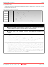
- USB (USB 1.1, full-speed)*
- LAN (10BASE-T)
Power supply to emulator Supplied from included AC adapter (power supply voltage: 100--240 V, 50/60 Hz)
* Available to connect the host machine that supports USB 2.0.
With the USB interface, not all hardware (such as host machine, USB devices, USB hub) combination will work and
guaranteed.