


M3062PT2-EPB User’s Manual 5. Troubleshooting
REJ10J0868-0200 Rev.2.00 January 16, 2006
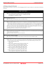
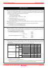
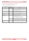
(2) MCU Setting Dialog Box Does Not Appear at Emulator Debugger Startup
Table 5.2 Checkpoints of errors at debugger startup
Error Checkpoint
Communication error occurred.
Data was not sent to the target.
Check all emulator debugger settings, interface cable settings and
switches on the rear of the PC7501 match.
See the user's manuals of PC7501 and emulator debugger.
User system cannot be properly built. (1) Download the proper firmware.
See "2.7 Downloading Firmware" (page 27).
(2) Recheck the connection between the PC7501 and this product.
See "2.4 Connecting the PC7501" (page 23).
Emulator’s version is not the same version as
the firmware in the target.
Download the proper firmware.
See "2.7 Downloading Firmware" (page 27).
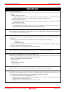
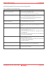
Target MCU is in the reset state. (1) Check the reset pin of the user system is pulled up.
(2) Check the reset pin of the user system has changed from "L" to "H"
level.
Target MCU cannot be reset. (1) Check that the NMI# pin is at “H” level.
(2) In memory expansion mode or microprocessor mode, check pins
RDY# and HOLD# are at “H” level.
(3) If the reset circuit of the user system has a watchdog timer, disable
the watchdog timer.
(4) Check that power is properly supplied to the user system and that the
user system is properly grounded.
Target is in "HOLD" state. (1) In memory expansion mode or microprocessor mode, check pins
RDY# and HOLD# at “H” level.
(2) The MCU is either in stop mode or wait mode. Either reset the MCU
or cancel the mode with an interrupt.
See MCU specifications.
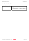
Target clock is stopped. When the clock is supplied from an external oscillator, check that the
oscillator circuit in the user system is oscillating properly.
Target MCU is not receiving power. Check that power is properly supplied to the user system and that the
user system is properly grounded.
Page 96 of 102