


M3062PT2-EPB User’s Manual Contents
REJ10J0868-0200 Rev.2.00 January 16, 2006
Contents
Page
Preface..........................................................................................................................................................................3
Important.......................................................................................................................................................................4
Precautions for Safety ..................................................................................................................................................6
Contents........................................................................................................................................................................9
User Registration........................................................................................................................................................11
Terminology................................................................................................................................................................12
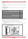
1. Outline.....................................................................................................................................................................13
1.1 Package Components...................................................................................................................................13
1.2 Other Tool Products Required for Development...........................................................................................14
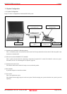
1.3 System Configuration ....................................................................................................................................15
1.3.1 System Configuration..........................................................................................................................15
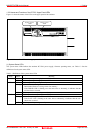
1.3.2 Names and Functions of the PC7501 Upper Panel LEDs..................................................................16
1.4 Specifications ................................................................................................................................................18
1.5 Operating Environment..................................................................................................................................19
2. Setup.......................................................................................................................................................................20
2.1 Flowchart of Starting Up the Emulator ..........................................................................................................20
2.2 Installing the Emulator Debugger (M16C R8C PC7501 Emulator Debugger) ..............................................21
2.2.1 Installing the Emulator Debugger........................................................................................................21
2.3 Connecting the Host Machine .......................................................................................................................22
2.4 Connecting the PC7501 ................................................................................................................................23
2.5 Connecting the Power Supply for the Emulator ............................................................................................24
2.6 Turning ON the Power...................................................................................................................................25
2.6.1 Checking the Connections of the Emulator System............................................................................25
2.6.2 Turning ON/OFF the Power ................................................................................................................25
2.6.3 LED Display When the Emulator Starts Up Normally .........................................................................26
2.7 Downloading Firmware..................................................................................................................................27
2.7.1 When It is Necessary to Download Firmware.....................................................................................27
2.7.2 Downloading Firmware in Maintenance Mode....................................................................................27
2.8 Self-check......................................................................................................................................................28
2.8.1 Self-check Procedure..........................................................................................................................28
2.8.2 If an Error is Detected in the Self-check..............................................................................................29
2.9 Connecting the User System.........................................................................................................................30
2.9.1 Connecting to an 80-pin 0.65-mm-pitch Foot Pattern.........................................................................31
2.9.2 Connecting to a 100-pin LCC Socket..................................................................................................32
2.9.3 Connecting to a 100-pin 0.65-mm-pitch Foot Pattern (Part 1)............................................................33
2.9.4 Connecting to a 100-pin 0.65-mm-pitch Foot Pattern (Part 2)............................................................34
2.9.5 Connecting to a 100-pin 0.65-mm-pitch Foot Pattern (Part 3)............................................................35
2.9.6 Connecting to a 100-pin 0.65-mm-pitch Foot Pattern (Part 4)............................................................36
2.9.7 Connecting to a 100-pin 0.5-mm-pitch Foot Pattern (Part 1)..............................................................37
2.9.8 Connecting to a 100-pin 0.5-mm-pitch Foot Pattern (Part 2)..............................................................38
2.9.9 Connecting to a 100-pin 0.5-mm-pitch Foot Pattern (Part 3)..............................................................39
2.9.10 Connecting to a 128-pin 0.5-mm-pitch Foot Pattern.........................................................................40
2.10 Switch Settings............................................................................................................................................41
2.10.1 Switch Settings of the JP1 ................................................................................................................41
2.10.2 A/D Conversion Bypass Capacitors..................................................................................................42
2.10.3 Pullup of Emulation Ports ..................................................................................................................43
2.11 Selecting Clock Supply................................................................................................................................44
2.11.1 Clocks................................................................................................................................................44
2.11.2 Using an Internal Oscillator Circuit Board.........................................................................................44
2.11.3 Using the Oscillator Circuit on the User System...............................................................................48
2.11.4 Using the Internal Generator Circuit..................................................................................................48
Page 9 of 102