


M3062PT2-EPB User’s Manual 3. Usage (How to Use the Emulator Debugger)
REJ10J0868-0200 Rev.2.00 January 16, 2006
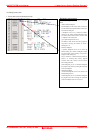
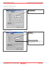
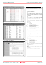
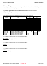
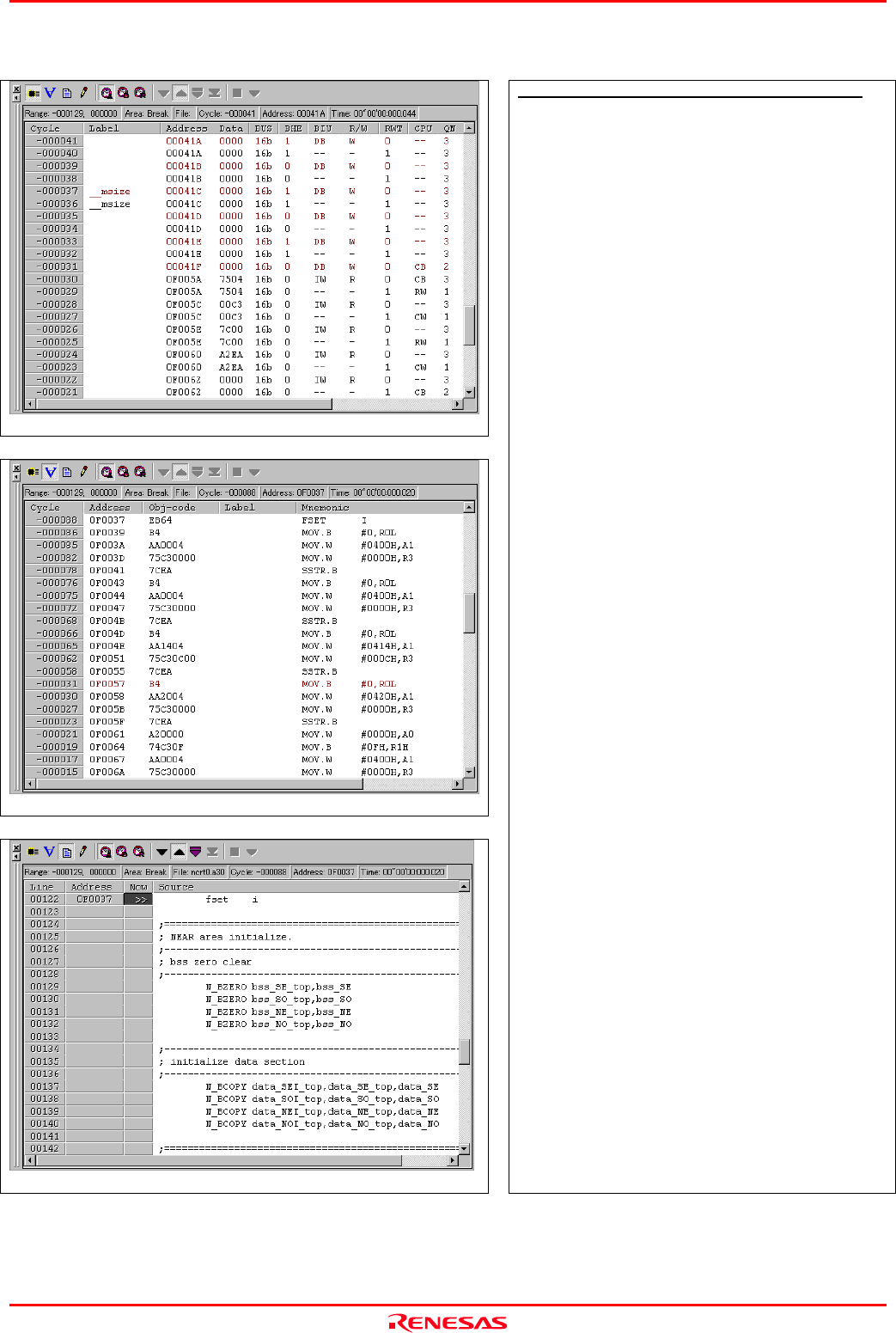
2. Trace window (Bus display)
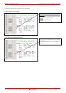
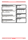
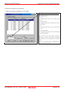
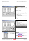
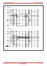
3. Trace window (Disassemble display)
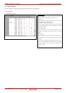
4. Trace window (Source display)
Explanation of the trace window (bus display)
The following explains the displayed contents, from left to right.
- Address
Shows the status of the address bus.
- Data
Shows the status of the data bus.
- BUS
Shows the width of the external data bus. In the present
emulator, “16b” for 16 bits wide bus and “8b” for 8 bits wide
bus are displayed.
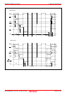
- BHE
Shows the status (0 or 1) of the BHE (Byte High Enable)
signal. If this signal = 0, the odd-address data is valid.
- BIU
Shows the status between the BIU (Bus Interface Unit) and
memory or I/O.
Symbol Status
- : No change
DMA : Data access except for CPU
INT : Starts INTACK sequence
IB : Instruction code read (bytes) by CPU
DB : Data access (bytes) by CPU
IW : Instruction code read (words) by CPU
DW : Data access (words) by CPU
- R/W
Shows the status of the data bus. Displayed as “R” for Read,
“W” for Write, and “–” for no access.
- RWT
This is the signal to indicate a valid bus cycle. When valid,
RWT = 0. The Address, Data, and the BIU signals are effective
when this signal is 0.
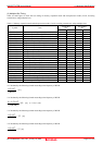
- CPU
Shows the status between the CPU and BIU (Bus Interface
Unit).
Symbol Status
CB : Op-code read (bytes)
RB : Operand read (bytes)
QC : Clears instruction queue buffer
CW : Op-code read (words)
RW : Operand read (words)
- QN
Shows the byte count stored in the instruction queue buffer.
The display range is 0 to 4.
- 76543210
Shows the level of external trace signal input cable EXTIN0 to
EXTIN7.
-
h” m’ s: ms. us
Shows the elapsed time after starting the user program.
Page 68 of 102