


M3062PT2-EPB User’s Manual 2. Setup
REJ10J0868-0200 Rev.2.00 January 16, 2006
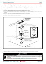
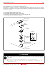
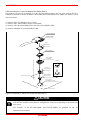
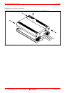
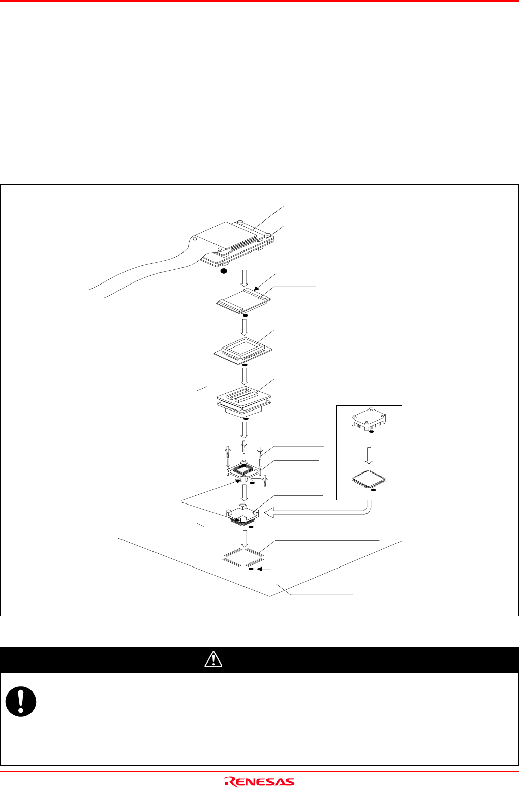
2.9.9 Connecting to a 100-pin 0.5-mm-pitch Foot Pattern (Part 3)
Here following is a procedure of connecting to a 100-pin 0.5-mm-pitch foot pattern on the user system using the M3T-FLX-
100NSD (not included). For details on the M3T-100LCC-DMS (not included) and M3T-FLX-100NSD (not included), refer to
each user's manual.
(1) Attach the M3T-FLX-100NSD to the user system.
(2) Attach the M3T-100LCC-DMS to the M3T-FLX-100NSD.
(3) Attach the CN2 side of the M30800T-PTC to the J4 side of the M3062PT2-EPB.
(4) Attach the M30800T-PTC to the M3T-100LCC-DMS.
Figure 2.16 Connecting to a 100-pin 0.5-mm-pitch foot pattern (Part 3)
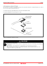
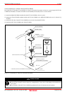
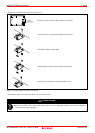
CAUTION
Notes on Connecting the User System:
Take care not to attach a converter board in a wrong direction. It may cause a fatal damage to the emulator and
user system.
The connectors of the M30800T-PTC are guaranteed for only 50 insertion/removal iterations.
The connectors of the M3T-100LCC-DMS and M3T-FLX-100NSD are guaranteed for only 20
insertion/removal iterations.
*
M3T-100LCC-DMS
(not included)
CN2 side
(3)
(4)
M30800T-PTC
(2)
(1)
100-pin 0.5-mm-pitch
No. 1 pin
User system
M3T-FLX-100NSD
(not included)
Flash version MCU etc.
Evaluation with
actual MCU
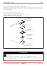
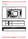
*: These four products are available in one package.
YQPACK100SD
NQPACK100SD-ND
HQPACK100SD
(not included)
YQ-GUIDE (x4)
These corners are not round.
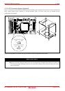
M3T-FLX160-EPB
M3062PT2-EPB
(PLQP0100KB-A) foot pattern
Page 39 of 102