


M3062PT2-EPB User’s Manual 2. Setup
REJ10J0868-0200 Rev.2.00 January 16, 2006
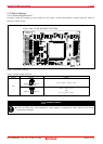
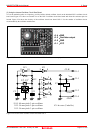
2.10 Switch Settings
2.10.1 Switch Settings of the JP1
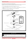
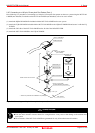
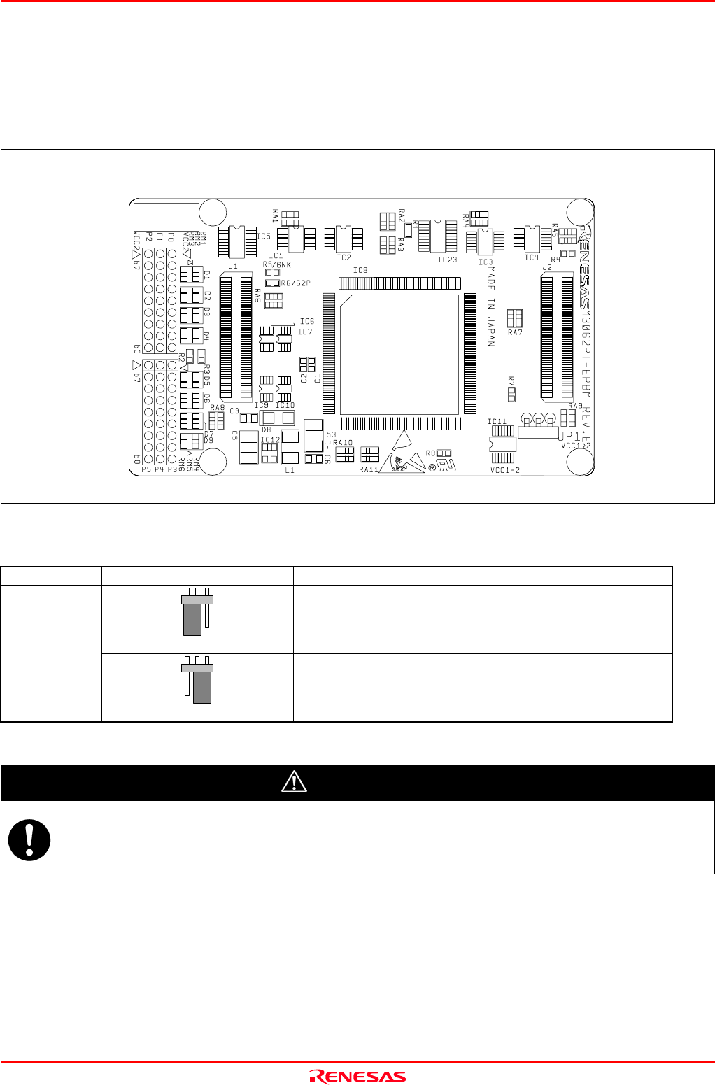
Set jumper switch JP1 according to a power supply you use. Figure 2.18 shows the positions of jumper switch JP1. Table 2.2
lists how to set the switch.
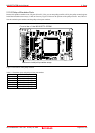
Figure 2.18 Position of the JP1
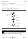
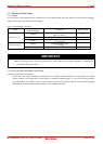
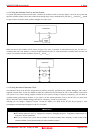
Table 2.2 Switch settings of the JP1
Switch Setting Voltage
VCC1=2 VCC1>2
(Factory-setting)
2.7 V ≤ Vcc1 = Vcc2 ≤ 5.5 V
JP1
VCC1=2 VCC1>2
Vcc1 = 5.0 ± 0.2 V
and
2.7 V ≤ Vcc2 < Vcc1
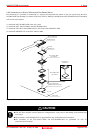
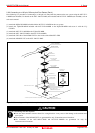
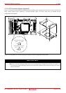
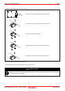
CAUTION
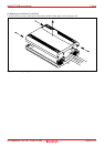
When Removing the Upper Cover:
Always shut OFF power when changing the switch settings or connecting the cables. Otherwise the internal
circuit may be damaged.
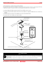
Front side of the M3062PT2-EPBM
JP1
512
Page 41 of 102