


( 16 / 76 )
IMPORTANT
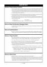
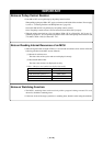
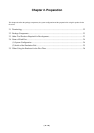
Notes on Pullup Control Resistor:
• Ports P00 to P57 are not pulled up by the pullup control resistor.
When pulling up the ports P00 to P57, apply a resistance to the inside of the emulator. How to apply
it, refer to "3.2 Setting Switches and Pullup Resistors" (page 29).
Note: Ports P60 to P107 are pulled up by the pullup control resistors.
Note: The pullup control resistors can read and write from P00 to P107 properly.
• When the pullup control resistor 1 (bit 1 of address 3FDh = PU11) of Ports P44 - P47 is set to "1"
(pulled up), ports P15 - P17 are pulled up regardless of the value of the pullup control resistor 0 (bit
3 of address 3FCh = PU03) of Ports P14 - P17.
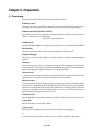
Note on Reading Internal Resources of an MCU:
• When the registers that are listed in Table 1.1 are read with an emulator, those results will be the
following (the data in the MCU are not effected).
(1) Results of real-time trace
The data values of the cycles read are not displayed correctly.
(2) Real-time RAM monitor
The data values read are not displayed correctly.
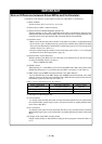
Table 1.1 Resisters and symbols not displayed normally
Resister Symbol
DMA source pointers 0, 1 SAR0, SAR1
DMA destination pointers 0, 1 DAR0, DAR1
DMA transfer counters 0, 1 TCR0, TCR1
DMA control resisters 0, 1 DM0CON, DM1CON
Notes on Watchdog Function:
• The MCU's watchdog timer can be used only while a program is being executed. To use it
otherwise, disable the watchdog timer.
• If the reset circuit of the target system has a watchdog timer, disable it when using the emulator.