


( 17 / 76 )
IMPORTANT
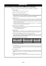
Note on Differences between Actual MCUs and the Emulator:
• Operations of the emulator system differ from those of actual MCUs as listed below.
(1) Reset condition
Set the rise time (0.2 Vcc to 0.8 Vcc) 1 µs or less.
(2) Initial values of MCU's internal resources
(3) Internal memories (ROM and RAM) capacities etc.
With this emulator system, "INT" (emulation memory ON) is the default for mapping areas
other than the SFR area (addresses 000h - 3FFh). For this reason, the emulation memory can
read and write in areas other than the SFR, internal RAM and internal ROM.
(4) Oscillator circuit
•Make note of the fact that in the oscillator circuit where a resonator is connected between
the XIN and XOUT pins, oscillation does not occur because a flexible cable, buffer IC and other
devices are used between the evaluation MCU and the target system. It is same for sub-clock
oscillator circuits (XCIN and XCOUT).
• For note on when using the oscillator circuit on the target system, refer to "3.3 (1) Using the
Oscillator Circuit on the Target System" (page 36).
(5) Characteristics of ports P00 to P57
With this product, ports P00 to P57 are connected via an emulation circuit. The device used
for the port emulation circuit is as follows.
Device: M60081L-0142FP
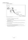
(6) HOLD* control
When inputting "L" to the HOLD* pin to run into the HOLD state, P00 to P52 will be in the
HOLD state delaying by 2.5 cycles than the actual MCU (see Figure 5.5 and Table 5.5).
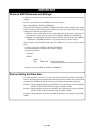
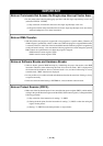
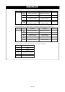
(7) DBC, Single-step and BRK instruction interrupt vector table addresses
You can download data to the DBC, Single-step and BRK instruction interrupt vector table
addresses. However, the data read out from this area is different from expected values, because
the emulator system uses this area (see Table 1.2).
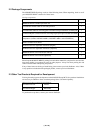
Table 1.2 Vector table addresses for the emulator
*1 Interruption for the debugger only
(8) A-D conversion
As a analog switch, flexible cable, pitch converter board and other devices are used between
the evaluation MCU and the target system, some characteristics are slightly different from
those of the actual MCU.
(9) D-A conversion
As a flexible cable, pitch converter board and other devices are used between the evaluation
MCU and the target system, some characteristics are slightly different from those of the actual
MCU.
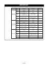
(10) Outputs of the actual MCU and this product
Outputs of this product are determined according to the user program as listed in Tables 1.3
to 1.6.
Factor of interruption Vector table addresses Data for reading
DBC*
1
FFFF4h - FFFF7h Indefinite
Single-step*
1
FFFECh - FFFEFh Indefinite
BRK instruction FFFE4h
- FFFE7h Indefinite