


( 27 / 76 )
Chapter 3. Setting Up
This chapter describes switch settings required for using this product and how to connect this product to the PC4701 and
the target system.
3.1 Removing the Upper Cover ........................................................................................................ 28
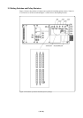
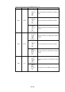
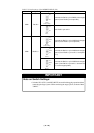
3.2 Setting Switches and Pullup Resistors ....................................................................................... 29
3.3 Selecting Clock Supply .............................................................................................................. 35
(1) Using the Oscillator Circuit on the Target System ............................................................... 36
(2) Changing the Internal Oscillator Circuit of the Emulation Pod............................................ 37
(3) Replacing the Oscillator Circuit Boards ............................................................................... 38
3.4 A-D Conversion Bypass Capacitor ............................................................................................ 39
3.5 Data Slicer I/O Signal and FSC Clock I/O Signal Circuit.......................................................... 40
3.6 Connecting the PC4701 .............................................................................................................. 41
(1) Connecting the Cable to the PC4701 .................................................................................... 41
(2) Connecting the Cable to the Emulation Pod ......................................................................... 42
3.7 Connecting the Target System.................................................................................................... 43
3.8 Making an MCU File for PD30 ..................................................................................................44