


( 62 / 76 )
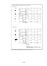
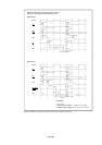
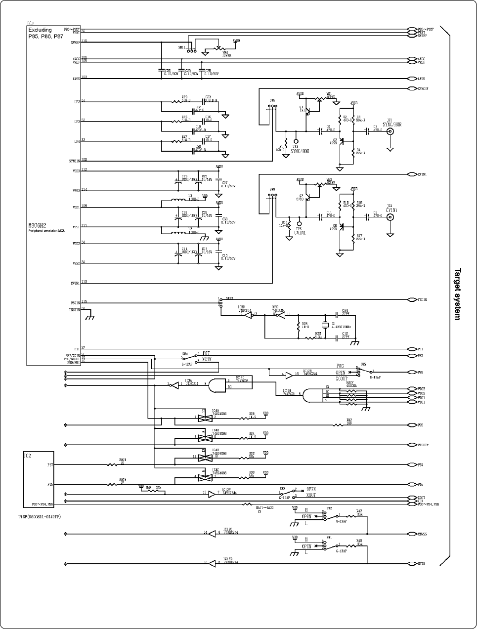
Figure 5.6 Connection diagram
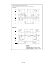
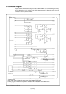
5.4 Connection Diagram
Figure 5.6 shows the connection diagram of the M306H2T-RPD-E. This connection diagram mainly
shows the interface section, and the circuits which are not connected to the target system such as the
emulator's control system are omitted.
*: Control signal
Each number of part indicates the part number of the M306H0T-PRT board.
However, only the numbers on the peripheral emulation MCU indicate the part numbers of the
M306H2T-RPDM board.