


( 23 / 74 )
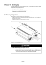
Chapter 3. Setting Up
This chapter describes switch settings required for using this product and how to connect this product to the PC4701 and
the target system.
3.1 Removing the Upper Cover ........................................................................................................ 24
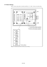
3.2 Switch Settings ........................................................................................................................... 25
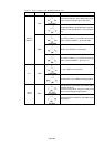
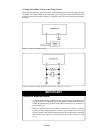
3.3 Selecting Clock Supply .............................................................................................................. 29
(1) Using the Oscillator Circuit on the Target System ............................................................... 30
(2) Changing the Internal Oscillator Circuit of Emulation Pod ................................................. 31
(3) Replacing the Oscillator Circuit Boards ............................................................................... 32
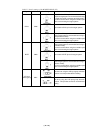
3.4 A-D Conversion Bypass Capacitor ............................................................................................ 33
3.5 Connecting the PC4701 and Emulation Pod .............................................................................. 34
(1) Connecting the Cable to the PC4701 .................................................................................... 34
(2) Connecting the Cable to the Emulation Pod ......................................................................... 35
3.6 Connecting the Target System.................................................................................................... 36
(1) Connecting 100-pin LCC Socket .......................................................................................... 37
(2) Connecting 100-pin 0.65-mm-pitch Foot Pattern (Part 1) .................................................... 38
(3) Connecting 100-pin 0.65-mm-pitch Foot Pattern (Part 2) .................................................... 39
(4) Connecting 100-pin 0.65-mm-pitch Foot Pattern (Part 3) .................................................... 40
(5) Connecting 100-pin 0.5-mm-pitch Foot Pattern (Part 1) ...................................................... 41
(6) Connecting 100-pin 0.5-mm-pitch Foot Pattern (Part 2) ...................................................... 42
(7) Connecting 144-pin 0.5-mm-pitch Foot Pattern ................................................................... 43