


( 40 / 74 )
(4) Connecting 100-pin 0.65-mm-pitch Foot Pattern (Part 3)
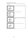
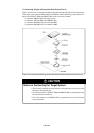
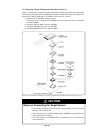
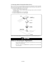
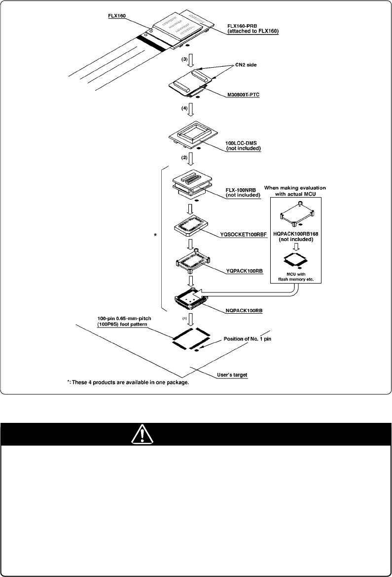
Figure 3.15 shows how to connect the emulation pod probe to the 100-pin 0.65-mm-pitch foot pattern
on the target system with the FLX-100NRB (not included), and here following is its procedure. For
details on the 100LCC-DMS and FLX-100NRB, refer to each user's manual.
(1) Attach the FLX-100NRB to the target system.
For details on how to attach the FLX-100NRB to the target system, see the user's manual of
the FLX-100NRB.
(2) Attach the 100LCC-DMS to the FLX-100NRB.
(3) Attach the M30800T-PTC to the FLX160-PRB.
(4) Attach the M30800T-PTC to the 100LCC-DMS.
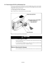
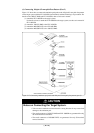
Figure 3.15 Connecting emulation pod probe and 100-pin 0.65-mm-pitch foot pattern (part 3)
CAUTION
Notes on Connecting the Target System:
• Take care not to attach the converter board in a wrong direction. It may cause a fatal
damage to the emulation pod.
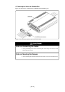
• The small connectors of 100LCC-DMS and FLX-100NRB are guaranteed for only
20 insertion/removal iterations.
• The small connectors of M30800T-PTC are guaranteed for only 50 insertion/
removal iterations.