


( 28 / 74 )
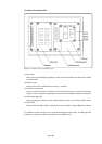
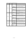
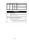
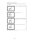
Table 3.3 Switch settings of the M30803T-RPD-E (3/3)
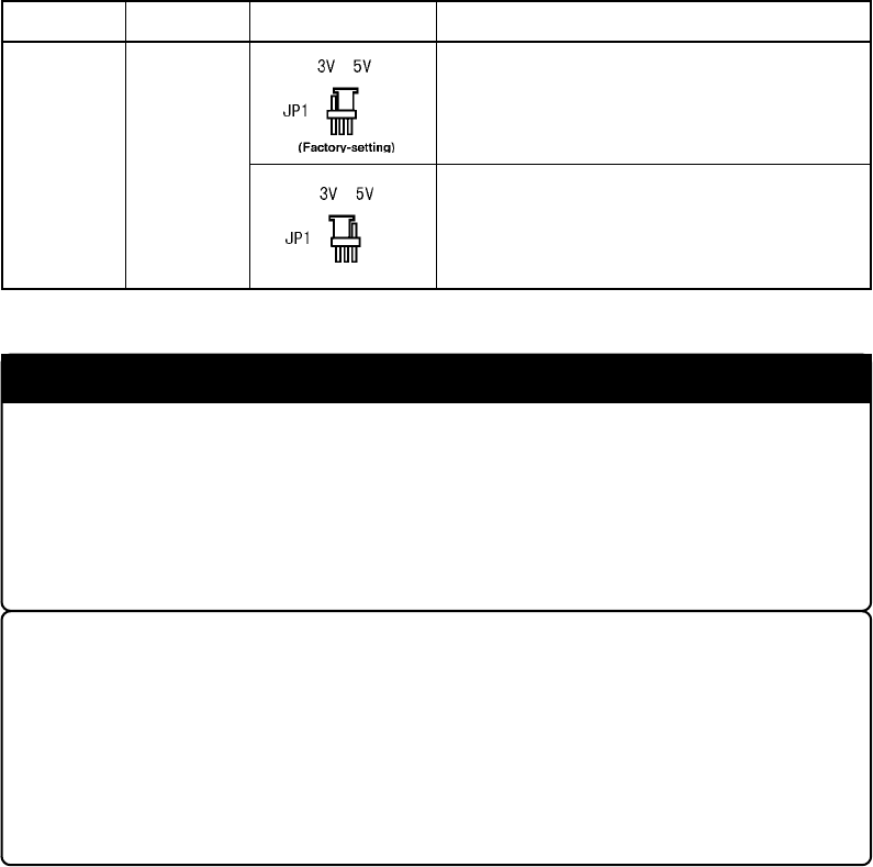
Signal Switch Setting Description
Voltage
JP1
M30803T-RPDM
Board
Set when using at the range of the voltage within
+4.2 to +5.5 V.
Set when using at the range of the voltage within
+2.7 to +4.2 V.
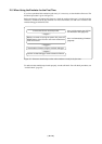
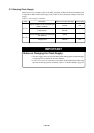
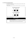
IMPORTANT
Note on Switch Setting:
•Switch settings of RDY*/HOLD*, CNVss and BYTE are provided to enable
debugging without connecting to the target system. When using the emulator
debugger in connection with the target system, set SW4 to the OPEN position and
SW5 and SW6 to the center position.
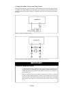
Note on Using A-D Input Group Selection:
• It is necessary to set the direction register of port P10 to input. Port P10 corresponds
to the pin that performs A-D conversion.
Example: To select A-D input for P00-P07, set the direction registers of P100-P107
and P00-P07 to input. Also, when the port P0 group and port P2 group are
selected for A-D input, port P10 cannot be used as an I/O port.