


( 52 / 74 )
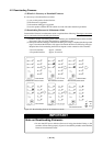
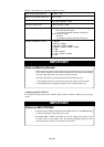
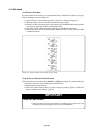
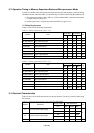
Table 4.3 Specifications of expansion emulation memory
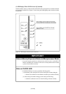
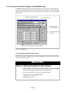
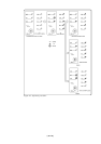
(5) Referring MCU STATUS
It is possible to confirm each level of BYTE, CNVss, RDY*, HOLD*, NMI* pins on the target
system.
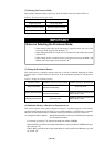
IMPORTANT
Notes on MCU STATUS:
• The status of pins of MCU is displayed in the "MCU STATUS" of the EMEM dialog.
Confirm if it matches with the processor mode.
• Check that "RDY", "HOLD" and "NMI" are set to "H". If they are set to the "L" level,
the MCU itself is in the standby state. The emulator debugger displays an error
message because it receives no response from the MCU.
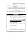
IMPORTANT
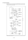
Note on Memory Access:
•When setting the processor mode to the memory expansion mode, it may be changed
to the memory expansion mode temporarily before the user program itself changes
from the single-chip mode to the memory expansion mode.
Take due consideration on this phenomenon in the following cases:
(1) Immediately before executing the program after setting a software break
(2) Immediately after stopping the program when a software break is set
Maximum operating frequency
Number of area which can be set
Area size
Emulation memory size
Possible bank to be set
Possible combination of areas
20 MHz, 1 wait
Max. 4 areas
Successive 256 KB or 1 MB
Total of 4 areas: 1.5 MB
(1) For area size 256 KB
X0h, X4h, X8h, XCh bank
e.g.) 20 bank, 64 bank, A8 bank, EC bank etc.
(2) For area size 1 MB
X0h bank
e.g.) 20 bank, 40 bank, 80 bank, A0 bank etc.
(1) 256 KB
(2) 256 KB + 256KB
(3) 256 KB + 256KB + 256KB
(4) 256KB + 256KB + 256KB + 256KB
(5) 1 MB
(6) 1 MB + 256 KB
(7) 1 MB + 256 KB + 256 KB
(8) none