4 Using the FoUSB
3) Connection Method
It specifies as a premise that MCU is carried on the Target Board.
(1) Connection order when using the USB bus-powered.
Connect in order of 2-4-3-1-host computer (PC).
(2) Separation order after using the USB bus-powered.
Connect in order of PC-1-3-4-2.
(3) Connection order when using external power supply.
Set a power source supply selector to the TARGET side.
Connect in order of PC-1-3-4-2 and finally supply power from outside.
(4) Separation order after using external power supply.
Drop the power which is supplied from outside.
Separate in order of PC-1-3-4-2.
4) The power source supply selector on the USB Monitor Board must be set differently
depending on the Target MCU used.
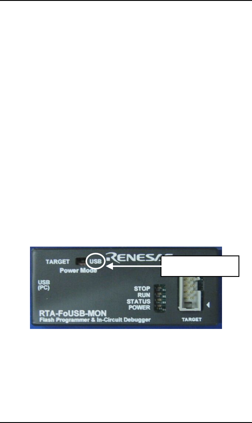
(1) When using 5 V
The power for the Target MCU is supplied from the USB Monitor Board.
Therefore, there is no need to supply power for the Target MCU from the Target
Board. In this case, set the power supply selector on the USB Monitor Board to
the USB side as shown in Figure 4-2.
When using 5 V, set the
switch to the USB side.
Figure 4-2 Power source supply selector-1
28


