


2-8 Riverstone Networks RS 2100 Switch Router Getting Started Guide
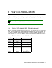
Hardware Overview RS 2100 Introduction
2.4 HARDWARE OVERVIEW
This section describes the RS 2100’s hardware specifications. For information on installing the hardware, see Chapter
3, "Hardware Installation."
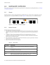
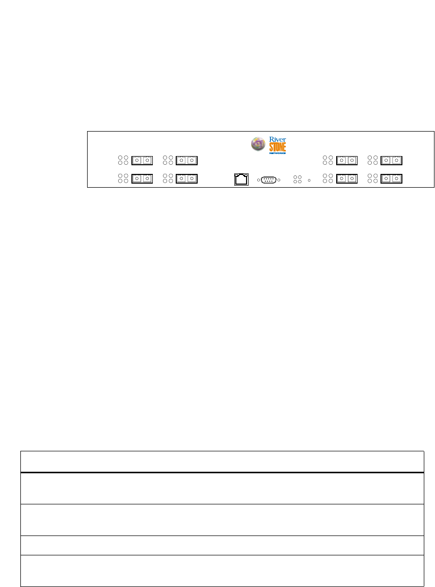
2.4.1 Chassis
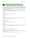
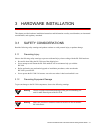
The RS 2100 chassis contains eight gigabit Ethernet (1000Base-SX) ports. The RS 2100’s configuration is fixed at
eight gigabit ports. No expansion modules are available. Figure 2-1 shows the front view of an RS 2100 chassis.
Figure 2-1 Front view of an RS 2100 chassis
2.4.2 External Controls
The RS 2100 has the following external controls:
• Male DB-9 Data Communications Equipment (DCE) port for serial connection from a management
terminal. Use this port to establish a direct CLI connection to the RS 2100. The default baud rate is
9600.
• 10/100Base-TX Data Terminal Equipment (DTE) port for in-band management. The port is
configured as Media Data Interface (MDI). Use this port to establish a management connection to
the RS 2100 over an Ethernet segment.
• Reset switch (RST). Use this switch to reboot the RS 2100 in the event of a system failure. The Reset
switch is recessed in the RS 2100’s chassis.
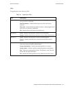
• Status LEDs, described in the following table:
Table 2-3 Status LEDs
LED Label Description
OK When this LED is on, the RS 2100 and all gigabit ports are functioning
correctly.
ERR When this LED is on, a fatal system error has occurred. Activate the RS 2100’s
boot PROM to reboot the router.
HBT This LED flashes when the RS 2100’s boot PROM is active.
DIAG When this LED is on, the RS 2100 is in diagnostic mode. (While in diagnostic
mode, several other LEDs on the RS 2100 are active, as well.)
CONSOLE
10/100 MGMT
4
21
Tx
Rx
Link
AN
Tx
Rx
Link
AN
G21-B
2
21
Tx
Rx
Link
AN
Tx
Rx
Link
AN
RST
OK
ERR DIAG
HBT
3
21
Tx
Rx
Link
AN
Tx
Rx
Link
AN
1
21
Tx
Rx
Link
AN
Tx
Rx
Link
AN
RS 2100