


3-4 Riverstone Networks RS 2100 Switch Router Getting Started Guide
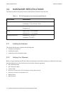
Hardware Specifications Hardware Installation
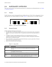
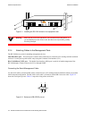
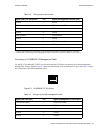
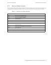
Figure 3-1 Installing the RS 2100 chassis in an equipment rack
Warning Make sure the screws are tight before your assistant releases the chassis. If
you accidentally leave the screws loose, the chassis can slip and fall, possibly
becoming damaged.
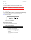
3.2.4 Attaching Cables to the Management Ports
The RS 2100 has two ports for attaching management devices:
Male DB-9 DCE port – This serial port is used for direct connection to a terminal or PC running terminal emulation
software. Use this port to perform basic setup using the Command Line Interface (CLI).
RJ-45 10/100Base-T DTE port – This Media Data Interface (MDI) port is used for in-band management of the
RS 2100 through a Telnet session to the CLI or through SNMP.
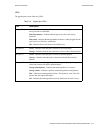
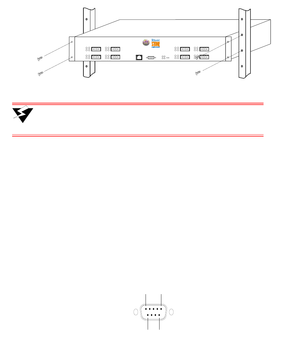
Connecting the Serial Management Cable
Use the serial cable to connect the RS 2100 to a terminal (or to a PC running terminal emulation software) to perform
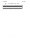
initial setup and configuration. The RS 2100’s serial cable is a female to female DB-9 crossover cable. Figure 3-2
shows the serial port’s pin-out. Table 3-2 maps the wiring of the serial cable
Figure 3-2 Serial port (DB-9 DCE) pin-out
CONSOLE
10/100 MGMT
4
21
Tx
Rx
Link
AN
Tx
Rx
Link
AN
G21-B
2
21
Tx
Rx
Link
AN
Tx
Rx
Link
AN
RST
SYS
OK
ERR DIAG
HBT
3
21
Tx
Rx
Link
AN
Tx
Rx
Link
AN
1
21
Tx
Rx
Link
AN
Tx
Rx
Link
AN
RS 2100
1
5
69