


Unit 3: Installation
CL408-412e Supplemental Manual
3-10 PN: 9001159A
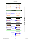
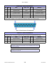
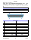
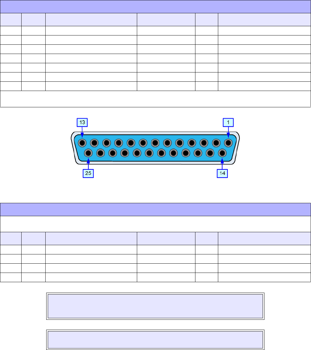
Figure 3-5, Serial Connector Pin Assignments
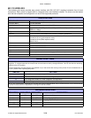
READY/BUSY CABLE REQUIREMENTS
DB9 DB25 HOST DIRECTION DB25 PRINTER
1 1 FG (Frame Ground) Bi-Directional 1 FG (Frame Ground)
2 3 RD (Receive Data) To Host 2 TD (Transmit Data)
3 2 TD (Transmit Data) To Printer 3 RD (Receive Data)
8 5 CTS (Clear To Send) To Printer DB9-6 4 RTS (Request To Send)
4 20 DTR (Data Terminal Ready) To Printer DB9-4 5 DSR (Data Set Ready)
6 6 DSR* (Data Set Ready) To Host 6 DTR (Data Terminal Ready)
5 7 SG (Signal Ground) Bi-Directional 7 SG (Signal Ground)
* This connection at the host side of the interface would depend upon the pin that is being used as the Ready/Busy signal by
the driving software. Typically, on a PC, it would be either CTS (pin5) or DSR (pin 6) on a DB-25 connector.
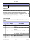
X-ON/X-OFF CABLE REQUIREMENTS
Communicates with the host to determine if the printer is ready to receive data by sending “XON” (HEX 11H) or “XOFF” (HEX
13H) code to the TD line. The single and multiple item buffers are switchable in the Interface Mode of the printer.
DB9 DB25 HOST DIRECTION DB25 PRINTER
1 1 FG (Frame Ground) Bi-Directional 1 FG (Frame Ground)
2 3 RD (Receive Data) To Host 2 TD (Transmit Data)
3 2 TD (Transmit Data) To Printer 3 RD (Receive Data)
5 7 SG (Signal Ground) Bi-Directional 7 SG (Signal Ground)
NOTE: Depending on the host used, it may be required to loop CS and RS
(maintaining at high-level) on the host side. For more information, refer to the host
computer documentation.
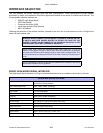
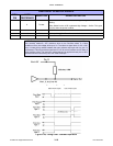
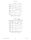
NOTE: Refer to the Charts & Diagrams unit of this manual to view timing charts for
Ready/Busy and X-ON/X-OFF.