


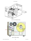

Unit 3: Installation
CL408-412e Supplemental Manual
3-13 PN: 9001159A
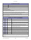
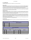
SOFTWARE SPECIFICATIONS
Corresponding Protocol TCP/IP
Network Layer ARP, RARP, IP, ICMP
Session Layer TCP, UDP
Application Layer LPD, FTP, TELNET, BOOTP, DHCP
NOTE: Print data can be sent by LPR and FTP of TCP/IP and dedicated socket protocol. Printer status is obtainable by
dedicated socket protocol.
NOTE: In the TCP/IP protocol enviroment, LPD and FTP are provided for printing; TELNET for variable setup; ARP, RARP,
and BOOTP/DHCP for address setup.
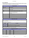
LPD protocol complies with RFC1179 and handles the list of logical printer name as queue name such as lp, sjis, euc. In
addition, a banner page can be printed by a proper setup.
When sending the job by LPR, the transmission order of data file/control file within the job will not affect print operation. In
addition, if the banner page is specified, it will be added to each data file. Job deletion by LPR is not available.
FTP protocol complies with RFC959 and handles the list of logical printer name as a transfer directory. File transfer to this
directory executes print operation. It is possible to specify ASCII(A), Binary(I) and TENEX(L8) as transfer mode - although the
mode difference is dependent on the client. A banner page may be printed with a proper setup.
TELNET Complies with RFC854. This operation consists of interactive menu form and enables change and reference of
internal setup, and to display status. To change the setup, enter “root” user and password at the time of login. Default of root
pasword is set as null (linefeed only).
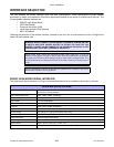
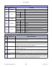
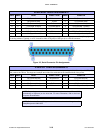
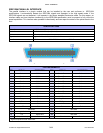
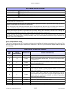
ACCESSORY (EXT) CONNECTOR PIN ASSIGNMENTS
DB-9 14 PIN DIRECTION SIGNAL DEFINITION
1 13 To Host Vcc +/- 5V
2 10 To Host
Ribbon Near End - Goes high when the amount of ribbon on the supply spindle is
approximately 46 feet (14m). The output will be low when the ribbon is completely
out.
3 4 To Host Error - Goes low when the printer detects an error condition.
4 7 To Printer
Reprint - Prints a duplicate of the last label of a print job when this signal is
received.
5 5 To Printer
Print Start - Prins a single label when this pin is pulled to ground. This signal must
be enabled to function by placing dipswitch DSW3-5 to the OFF position.
6 6 To Host
End Print - Is used to drive an applicator or other external device requiring
synchronization with the print cycle. Four types of output signals may be chosen
by using dipswitches DSW3-6 and DSW3-7.
7 1 To Host Label Out - Goes low (0V) when a label error exists.
8 3 To Host Ribbon Out - Goes low (0V) when ribbon supply is out.
9 2 Reference Signal Ground.
8 To Printer Isolated Power Source - for signal input.
9 To Host
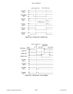
Mode 1: High voltage on LCD is selected = online, print job waiting.
Mode 2: High voltage on LCD is selected = online. Goes low (0V) when offline.
11 Reserved.
12 To Host +24V +/- 10% @ 2A - Power for external devices.
14 Frame Ground
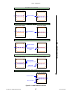
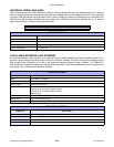
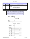
NOTE: The signals on pins 1, 3, 4, 6, 9, and 10 each have an open collector output. These pins normally measure +.07V maximum when a
true condition exists. If a false condition ocurrs, the voltage will drop to 0V. To achieve a signal level of +5V, you must add a 330 ohm, 1/4 watt,
pull-up resistor between the open collector output pin and Vcc (pin 13) as illustrated. This will provide a signal level of +5V for a true condition
and 0V when a false condition exists. The maximum voltage that can be applied to these pins is +50V and the maximum current they can sink
is 500 milliamps.