Unit 4: Printer Configuration
CL408-412e Supplemental Manual
4-3 PN: 9001159A
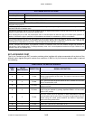
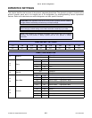
DIPSWITCH SETTINGS
This chapter identifies the functions of the printer’s integrated dipswitches. The dipswitch complex is located on the
printer’s operator panel and is an integral part of its configuration by enabling/disabling various operational
features. Refer to the table below on switch designation and their specific functions.
ATTENTION: Each dipswitch must be set for the printer to properly function. Address
all eight switches individually, but some may not require change.
NOTE: A small, flat tool similar to a screwdriver is required to alter dipswitch position.
When changing a switch setting, ensure that it has been moved fully up or down.
NOTE: The switches are arranged horizontally, from left to right, and oriented
vertically. The ON position is always upward and the OFF position is always
downward.
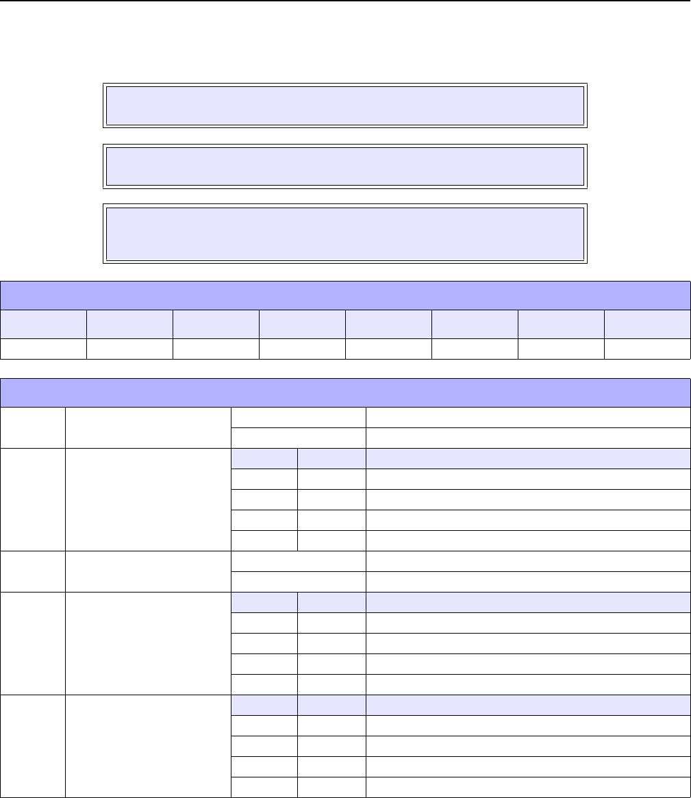
DSW1 DEFAULT SETTINGS
1-1 1-2 1-3 1-4 1-5 1-6 1-7 1-8
OFF OFF OFF OFF OFF OFF OFF OFF
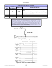
DSW1 CONFIGURATION
1-1 Data BIt
OFF 8 Data Bit
ON 7 Data Bit
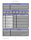
1-2
1-3
Parity
1-2 1-3
ON ON Reserved
ON OFF Odd
OFF ON Even
OFF OFF None
1-4 Stop Bit
OFF 1 Stop Bit
ON 2 Stop Bit
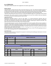
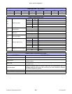
1-5
1-6
Baud Rate
1-5 1-6
ON ON Normal: 2400, High Speed: 57600
ON OFF Normal: 4800, High Speed: 38400
OFF ON Normal: 19200, High Speed: 19200
OFF OFF Normal: 9600, High Speed: 9600
1-7
1-8
Protocol
1-7 1-8
ON ON Status 4
ON OFF Status 3
OFF ON XOn / XOff
OFF OFF Ready / Busy


