Unit 3: Installation
CL408-412e Supplemental Manual
3-16 PN: 9001159A
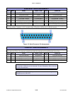
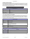
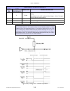
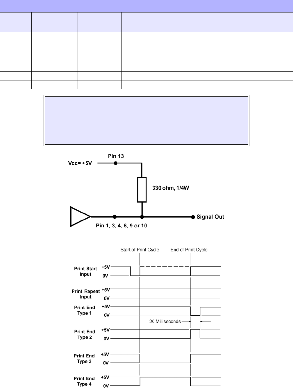
Figure 3-7, Signal Diagram
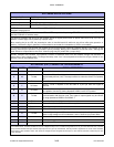
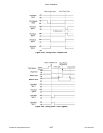
Figure 3-8a, Timing Chart - Standard Operation
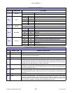
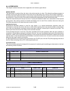
9To Host
When Mode1 on the LCD is selected High Voltage = Online Print Job
Waiting.
When Mode2 on the LCD is selected High Voltage = Online. This goes
low (0V) when the printer is offline.
11 Reserved.
12 To Host +24V +/- 10% @2A - Power for external devices.
14 Frame Ground
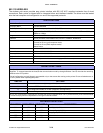
NOTE: The signals on pins 1, 3, 4, and 10 each have an open collector output. These
pins normally measure +.07V maximum when a true condition exists. If a false
condition occurs, the voltage will drop to 0V. To achieve a signal level of +5V, a 330
ohm, 1/4 watt pull-up resistor between the open collector output pin and Vcc (pin 13)
as illustrated. This will provide a signal level of +5V for a true condition and 0V when a
false condition exists. The maximum voltage that can be applied to these pins is +50V
and the maximum current they can sink is 500 milliamps.
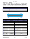
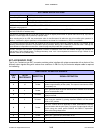
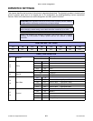
READY/BUSY INTERFACE SIGNALS
DB-9
PIN
14 PIN
CENTRONICS
DIRECTION SIGNAL DEFINITION


