


27
9. Diagnostics
9. 2. Available information
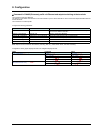
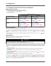
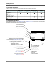
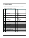
In addition to the LEDs, the table below summarizes the diagnostic information available by various means.
9. 3. Monitoring the control
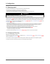
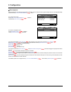
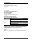
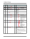
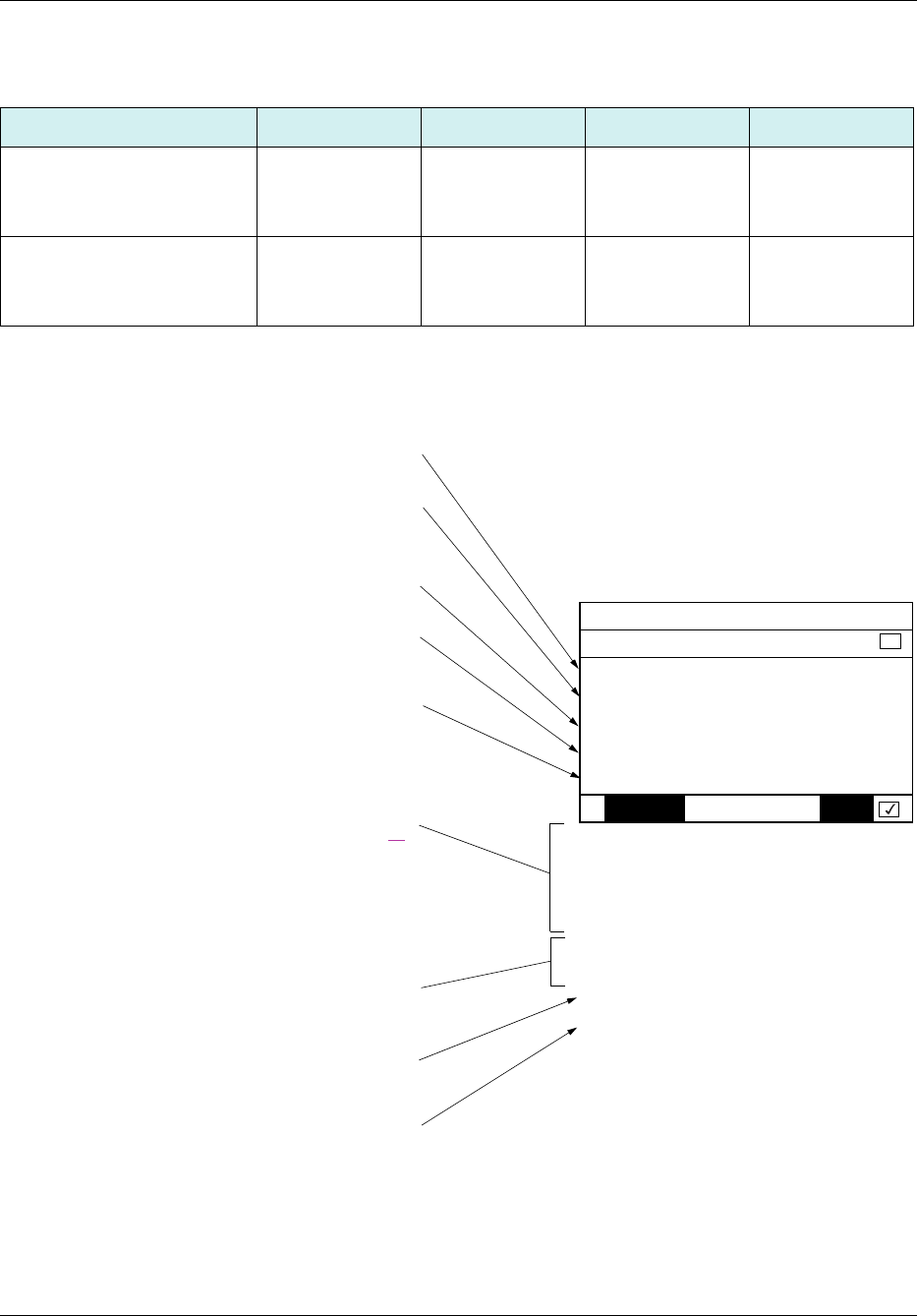
On the graphic display terminal only, the [1.2 - MONITORING] menu, [COMMUNICATION MAP] submenu can be used to display control
signal diagnostic information between the drive and the Ethernet PLC:
Functions Graphic display
terminal
Integrated display
terminal
PowerSuite software
workshop
Standard
web server
Control-signal diagnostics
• Control word
• Setpoint
• Active channel
•Etc.
p
ppp
Communication diagnostics
• Transmission counter
• Reception counter
• Collision counter
•Etc.
pp
RUN NET +50.00 Hz 80A
COMMUNICATION MAP
Command Channel : Com. card
Cmd value : 000F
Hex
Channel ref. active : Com. card
Frequency ref. : 500.0
Hz
Status word : 8627
Hex
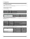
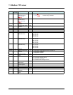
Code Quick
W3204 : 53
W3205 : 725
W7132 : 0000
Hex
W0 : -----
Hex
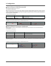
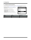
COM. SCANNER INPUT MAP
COM SCAN OUTPUT MAP
CMD. WORD IMAGE
FREQ. REF. WORD MAP
MODBUS NETWORK DIAG
MODBUS HMI DIAG
CANopen MAP
SCANNER CARD PROG.
Active command channel
Value of control word used
to send a command to the drive
(hexadecimal format)
Active setpoint channel
Value of frequency setpoint
(unit 0.1 Hz) used to control the drive
Value of status word
(hexadecimal format)
Values of the four monitored words selected by the user.
The address and display format of these parameters
can be configured in the [6 - MONITORING CONFIG.] menu,
[6.3 - COM. MAP CONFIG.] submenu
(see “Configuration” section on page 16
).
The value of a monitored word is equal to “-----” if:
- Monitoring has not been activated
(address equal to W0)
- The parameter is protected
- The parameter is not known (e.g., W3200)
Communication scanner:
Use not recommended for Ethernet
for performance reasons
Control word from Ethernet
[COM. card cmd.] (CMd3)
Frequency setpoint from Ethernet
[Com. card ref.] (LFr3)