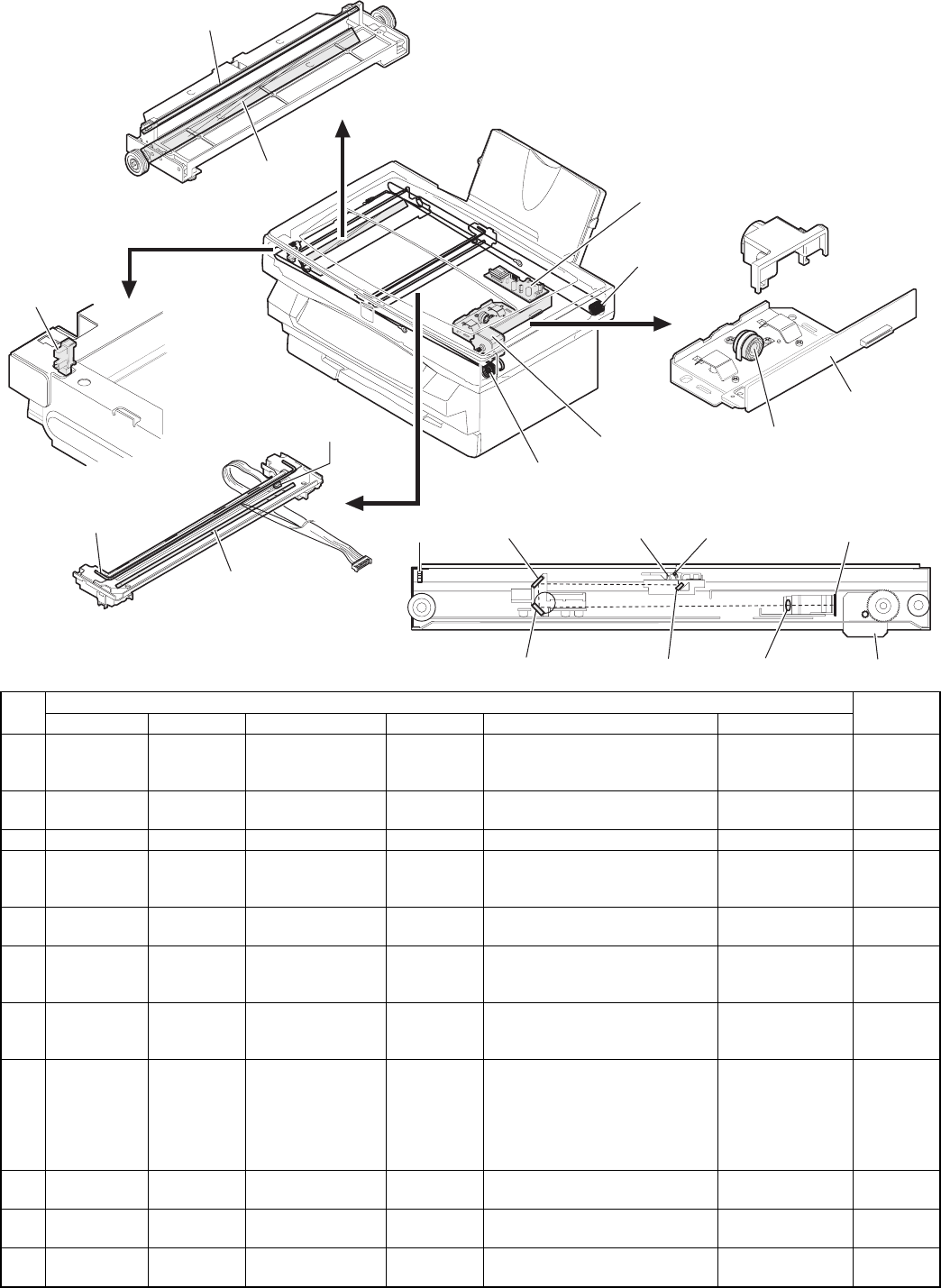
(2) Major parts
No.
Parts
Note
Code Signal name Name Type Function/operation Active condition
1 Scanner lamp
control PWB
Drives the scanner lamp.
Maintains the lamp light quantity
at a constant level.
2 Scanner drive wire Transmits the scanner motor
power to the scanner unit.
3 Scanner motor Drives the scanner unit.
4 MHPS MHPS Scanner home
position sensor
Photo
transmission
sensor
Detects the scanner home
position. By this signal the image
scanning operation is controlled.
HIGH (5V) when
the home position
is detected.
5 Lens Transfers the document image to
CCD.
6 CCD
SENSOR
CCD OUT CCD (Image)
sensor
CCD Scans the document images
(photo signals) and converts
them into electrical signals.
Digital signal
(8Bit)
7 Scanner lamp Radiates light to the document to
allow the CCD to scan the
document images.
8 SL SENSOR PDA/PDK Scanner lamp light
quantity sensor
Photo diode Detects the scanner lamp light
quantity. This signal is inputted to
the scanner lamp control PWB to
control the scanner lamp drive
voltage to maintain a constant
level of light quantity.
Analog signal
(0 ∼ 0.5V)
9 No. 1 mirror Leads the document image to
CCD.
10 No. 2 mirror Leads the document image to
CCD.
11 No. 3 mirror Leads the document image to
CCD.
10)
11)
4) MHPS
8) SL SENSOR
9)
7)
6) CCD SENSOR
5)
4) MHPS
10) 8) SL SENSOR 7) 6) CCD SENS
OR
11) 9) 5) 3)
2)
3)
2)
1)
4) MHPS
1 – 10


