G. Electrical section
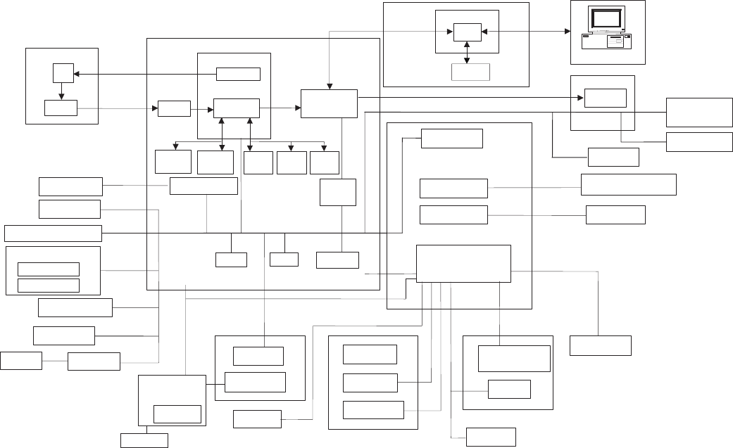
(1) Block diagram
a. Major sections operations and functions
MCU (PCU) PWB
The CPU controls the engine, and the ASIC performs image process.
Image data (analog signals) from the scanner (reading) section are
converted into digital signals by the A/D convertor and image process
(area separation, filter process, gamma correction, resolution conver-
sion, zooming) is performed by the ASIC and the line memory
(SRAM). The processed data are outputted to the scanner (writing)
section.
During printing, the dot image data from the ICU PWB are received
and outputted to the scanner (writing) section straightly. The CPU
controls the machine operations according to the key operation sig-
nals from the operation PWB. The loads (motor, lamp. solenoid, high
voltage power PWB, etc.) are controlled according to the sensors and
detectors signals. At the same time, the machine status data are
outputted to the operation section and the ICU PWB.
CCD PWB
CPU
H8S
DRAM
ASIC
I/F
A/D
EEPROM
RAMROM
SRAM
32kX8
SRAM
32kX8
Power SW
DRAM
16Mbit
DRAM
16Mbit
DRAM
16Mbit
MCU (PCU) PWB
Image process ASIC
CCD control
Data select
Motor driver
ICU PWB
Paper in sensor
High voltage
PWB
Driver
Motor driver
High voltage unit
Main charger roller
Drum
OPC cartridge
LSU unit
Laser
Pickup solenoid
Main motor
Transfer roller
Polygon motor
CCD
Amplifier
Scanner motor
FAN motor
Home position sensor
Paper size sensor
Toner sensor
Invertor
Scanner
lamp
Image
process
Heat roller
Thermistor
Heater lamp
Power PWB unit
Developer cartridge
Doctor
Earth sheet
Developing
roller
Control
electrode
Paper exit
sensor
Laser beam
sensor
Operation panel PWB
Key switch
Display lamp
Temperature
fuse
Temperature
fuse
1 – 28


