


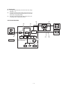
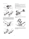
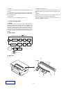
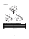
* CCD unit
Images (light) is converted into an electrical signal (analog signal) by
the CCD.
The image signal read by the CCD is converted into a digital signal b
the A/D convertor in the MCU PWB and outputted to the ASIC, where
the image is processed.
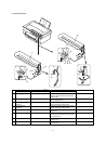
* Scanner motor
The scanner unit is driven by the scanner drive motor.
* Scanner home position sensor
The scanner home position sensor senses the scanner position. The
copy image position control is performed by the sensing timing of this
sensor.
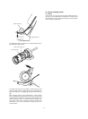
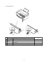
* Zooming
Zooming is performed by changing the copy magnification ratio in the
sub scanning direction or changing the scanning speed.
The copy magnification ratio in the main scanning direction is
changed by the software in the ASIC.
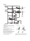
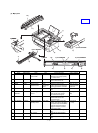
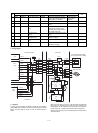
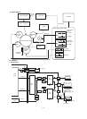
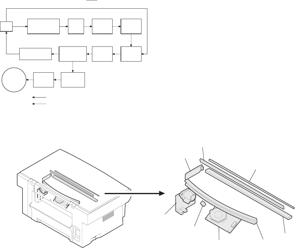
C. Scanner (writing) section
(1) Outline
In this section, the dot image data sent from the MCU PWB are
converted into laser beams (ON/OFF), which are scanned to form
latent electrostatic images on the OPC drum. It is composed of the
laser beam generating section (where dot image data signals are
converted into laser beams (ON/OFF)), the laser beam correction
section, the laser beam scanning section, and the laser beam detect-
ing section. The major parts and their functions are described in the
following.
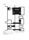
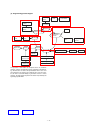
(2) Block diagram
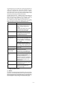
(3) Major parts
VIDEO
SYNC
(PCU)
MCU
Scanning motor drive signal (PMD, PMCLK)
Laser diode
control circuit
Laser
diode
Collimator
lens
No. 1
cylinder
lens
Laser beam
sensor
No. 2
reflection mirror
(curved mirror)
No. 1
reflection
mirror
Motor
mirror
Drum
No. 2
cylinder
lens
No. 3
reflection
mirror
Signal
Laser beam
2)
1) SYNC
8)
7)
6)
5)
4)
3)
1 – 12