


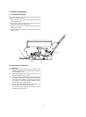
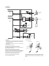
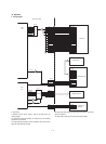
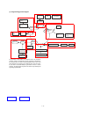
(3) Operation
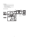
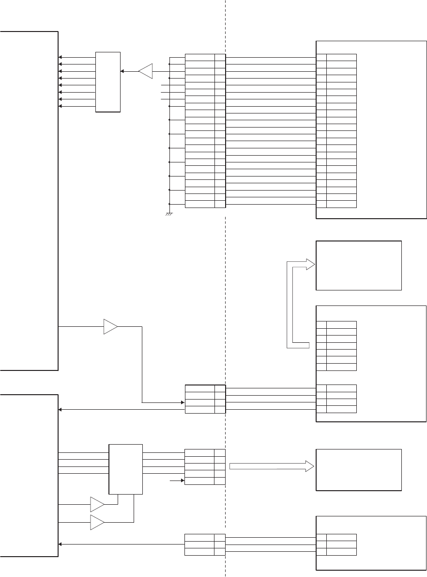
a. Wiring diagram
* Copy lamp
A cathode ray tube (Xenon lamp) is used as the light source for
reading images.
To maintain the lamp light quantity at constant level, the following
operations are performed.
The copy lamp light quantity sensor is provided in the scanner unit to
detect the copy lamp light quantity.
The copy lamp drive voltage corresponding to the sensor output level
(CLIN) is outputted.
The copy lamp is driven by the scanner lamp control PWB.
GND 1
A-GND 2
CCDOUT 3
A-GND 4
A5V 5
5V 6
12V 7
f1 9
GND 10
GND 8
f2 11
GND 12
SH- 13
GND 14
RS 15
GND 16
SP 17
CP 19
GND 20
GND 18
NC 21
GND 22
5V
12V
A/D
D-GND 1
A-GND 2
CCDOUT 3
A-GND 4
A5V 5
5V 6
12V 7
f1 9
D-GND10
D-GND 8
f211
D-GND12
SH-13
D-GND14
RS15
D-GND16
SP17
CP19
D-GND20
D-GND18
NC21
D-GND22
CFL-H 1
2
3
FGND 4
PDA 5
PDK 6
CFL-L 7
24V 1
P-GND 2
ON/OFF 3
PD 4
24V 1
P-GND 2
CL-CNT 3
CL-IN 4
MRMT0 1
2
3
4
5
GND 1
MHPS 2
5V 3
GND 1
MHPS 2
5V 3
MRMT1
MRMT2
MRMT3
24V-mir
DRIVER
24V
MCU(PCU) PWB
CCDD1
CCDD0
CCDD2
CCDD3
CCDD4
CCDD5
CCDD6
CCDD7
IC112
ASIC
IC8
5V
CCD UNIT
CPU
IC5
CLCNT
IC13
(Not used)
MRMT0
MRPS1
MRPS2
MHPS
MRMT1
MRMT2
MRMT3
RAMP UNIT
CN2
CN1
INVERTER UNIT
SCANER MOTOR
SCANER H.P
SENSOR
CN10
1 – 11