


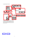
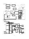
(3) Operation
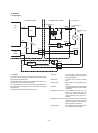
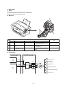
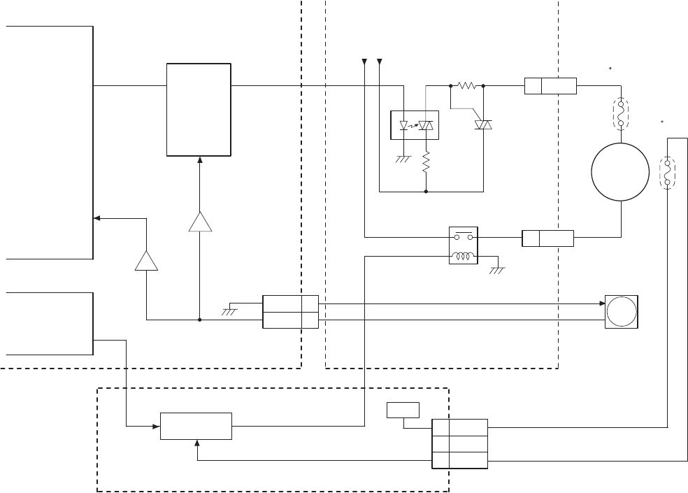
a. Wiring diagram
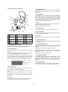
b. Operation
The heater lamp ON/OFF is controlled by the detection signal (volt-
age value) from the thermistor to maintain the heat roller surface
temperature at the optimum level.
The heat roller surface temperature is controlled to 160/155 ˚C in the
print mode and to 80 ˚C in the pre-heat mode.
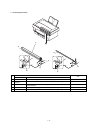
As a protective measure in case of abnormally high temperature in
the fusing section, two temperature fuses are provided in the heater
lamp power line.
The heater lamp is lighted by the AC power source.
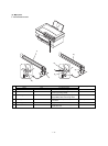
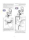
Heat roller: The heat roller is made of aluminum
tube coated with teflon to provide a good
separation capability.
Heater lamp: A halogen lamp is used as the heater
lamp.
Pressure roller: Silicon rubber is used to provide enough
pressure.
Thermistor: A chip-type thermistor of good response
is used to detect the heat roller surface
temperature.
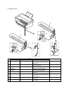
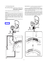
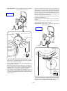
Temperature fuse (132 ˚C): The temperature fuse (132 ˚C) is at-
tached to the fusing cover. When the
fusing cover ambient temperature be-
comes abnormally high, this fuse is
blown off.
Temperature fuse (187 ˚C): The temperature fuse (187 ˚C) is closely
attached to the heat roller. When the
heat roller temperature becomes abnor-
mally high, this fuse is blown off.
Separation pawl: The separation pawl separates paper
from the heat roller mechanically.
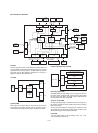
CPU
HLON
HLON-
RTH
HLL
1/3
CN603
(IC5)
HLN
2/4
CN603
GND
1
CN2
2
RTHN
COMP
AMP
AC POWER IN
PR
RTH
+24V
1
CN801
2
NC
3 +24VS
DRIVER
PR
ASIC
(IC202)
+24V
MCU(PCU) PWB POWER SUPPLY PWB
Gate
Temperature fuse
(132 C)
Fusing section
Temperature fuse
(187 C)
Heater
lamp
Thermistor
High voltage power PWB
1 – 26