


AN93
130 Rev. 1.3
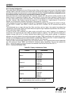
Given the example initialization settings shown in Table 87, after an ATDT command has been sent to establish a
connection, the modem responds with the following:
ATDT12345
CONNECT 1200
PROTOCOL: NONE
<0x19> <0xBE> <0x20> <0x20> <0x19> <0xB1>
The first <EM><rate> indicator shows that the modem connected with a transmit rate of 1200 bps and a receive
rate of 1200 bps. The <EM><flag> that occurs immediately after the <EM><rate> indicates that a non-flag to flag
transition has occurred and that the receiver has now been synchronized. An <EM><flag> indicator is applicable
only to the first occurrence of a non-flag to flag transition. Future occurrences of non-flag to flag transitions are
indicated with an <EM><err> instead. Also, this feature is unique to the U87 [8]=1 option. Also, with U87 [8]=1, the
Framed Submode is entered immediately upon connection. Otherwise, if U87 [8]=0, the Transparent Submode is
entered instead, and the host is expected to send an <EM> <flag> to switch to the Framed Submode.
After a connection has been established, the modem is ready to transmit and receive frames. For example, if it is
desired to send a frame whose contents are:
<0x10><0x11><0x12><0x13><0x14><0x15>
The host software sends the following:
<0x10><0x19><0xA0><0x12><0x19><0xA1>
<0x14><0x15><0x19><0xB1>
Note the bytes <0x11> and <0x13> are <EM> shielded because these bytes could have been used for XON /
XOFF handshaking. In this example, CTS/RTS hardware handshaking is used, so it is also possible for the host to
have sent this series of bytes instead:
<0x10><0x11><0x12><0x13><0x14><0x15>
<0x19><0xB1>
However, if the host does not <EM> shield the 0x11 and 0x13 characters, XON / XOFF software handshaking can
no longer be used.
In either of the above transmit frames, the <EM><flag> is used to indicate that a logical frame has completed. The
modem does not begin transmitting the frame at the DCE until the <EM><flag> is received or the number of bytes
sent to the modem exceeds the number of bytes programmed into U87 [7:0].
In the above example, the following transmission:
<0x10><0x19><0xA0><0x12><0x19><0xA1>
<0x14><0x15><0x19><0xB1>
meets both criteria of having 10 bytes received at the DTE and receipt of an <EM><flag> command. In this
example, the transmission at the DCE begins approximately after the receipt of the <0xB1> byte.
Once an HDLC frame begins transmitting at the DCE, the host must ensure transmit overrun and underrun do not
occur. It is expected that the +ITF command be used to adjust the transmit flow control thresholds so that it is tuned
to the system's ability to process the interrupt.
If a transmit underrun occurs, the <EM><tunder> indicator always appears in the receive path, regardless of how
+ESA[C] is programmed.
If +ESA[C] = 0, the modem transmits an abort character at the DCE at the point of the transmit underrun. Additional
transmit frames can then be transmitted normally.
If +ESA[C] = 1, the modem transmits an HDLC flag at the point of the transmit underrun, and the DCE continues to
send only HDLC flags until the host sends an <EM><resume> command. The <EM><resume> is then followed by
the <EM><unum> command so that the host software can correct this problem.
A transmit overrun can occur if the host does not properly implement transmit flow control. When a transmit
overflow occurs, the <EM><tover> indicator always appears in the receive path. A transmit overflow is considered
to be a catastrophic failure and results in non-deterministic behavior at the DCE. It is recommended that the
session be terminated immediately.