


AN93
Rev. 1.3 217
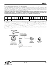
7.7.3.3. Speakerphone Calibration—AEC Gain Calibration
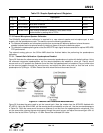
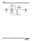
Figure 36 illustrates the setup used to set AEC speaker reference gain (U19C) and the AEC microphone input
signal gain (U19D). Here the modem has the AEC/AES enabled (AT+VSP=1) with the calibrated UB1 and UB5
values, which where obtained from the two previous sections. Using the Si24xx-VMB, call the remote phone and
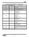
establish a voice call. Use the command sequence in Table 135.
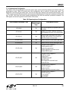
The AECREF (U19E) contains the energy information of both the AEC speaker reference signal (SPKREF) and the
microphone signal (MICREF). The SPKREF bits represent the AEC speaker reference energy, and MICREF bits
represent the AEC microphone input energy. The energy value is computed from average(s[t]^2).
Send the white noise from the remote phone so that the energy level at the meter (Tip and Ring) is -15dBm. Use
the AT:R19E command to read the contents of the U19E register. Adjust the AEC gain (U19C) of the speaker
reference signal until SPKREF reaches a value as close to 0x38 as possible. Adjust the AEC gain (U19D) of the
microphone input signal until MICREF has a value as close as possible to 0x38.
U19C and U19D are calibrated when the AT:R19E reading is close to 0x3838, with a power-level difference of less
than 2dB. Record these values and use them in the initialization sequence defined in Table 119, “Initialization
Sequence,” on page 194.
Figure 36. AEC Gain Calibration
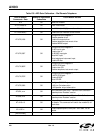
Reg. Name Bit
15
Bit
14
Bit
13
Bit
12
Bit
11
Bit
10
Bit
9
Bit
8
Bit
7
Bit
6
Bit
5
Bit
4
Bit
3
Bit
2
Bit
1
Bit
0
U19E AECREF SPKREF MICREF