


AN93
248 Rev. 1.3
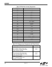
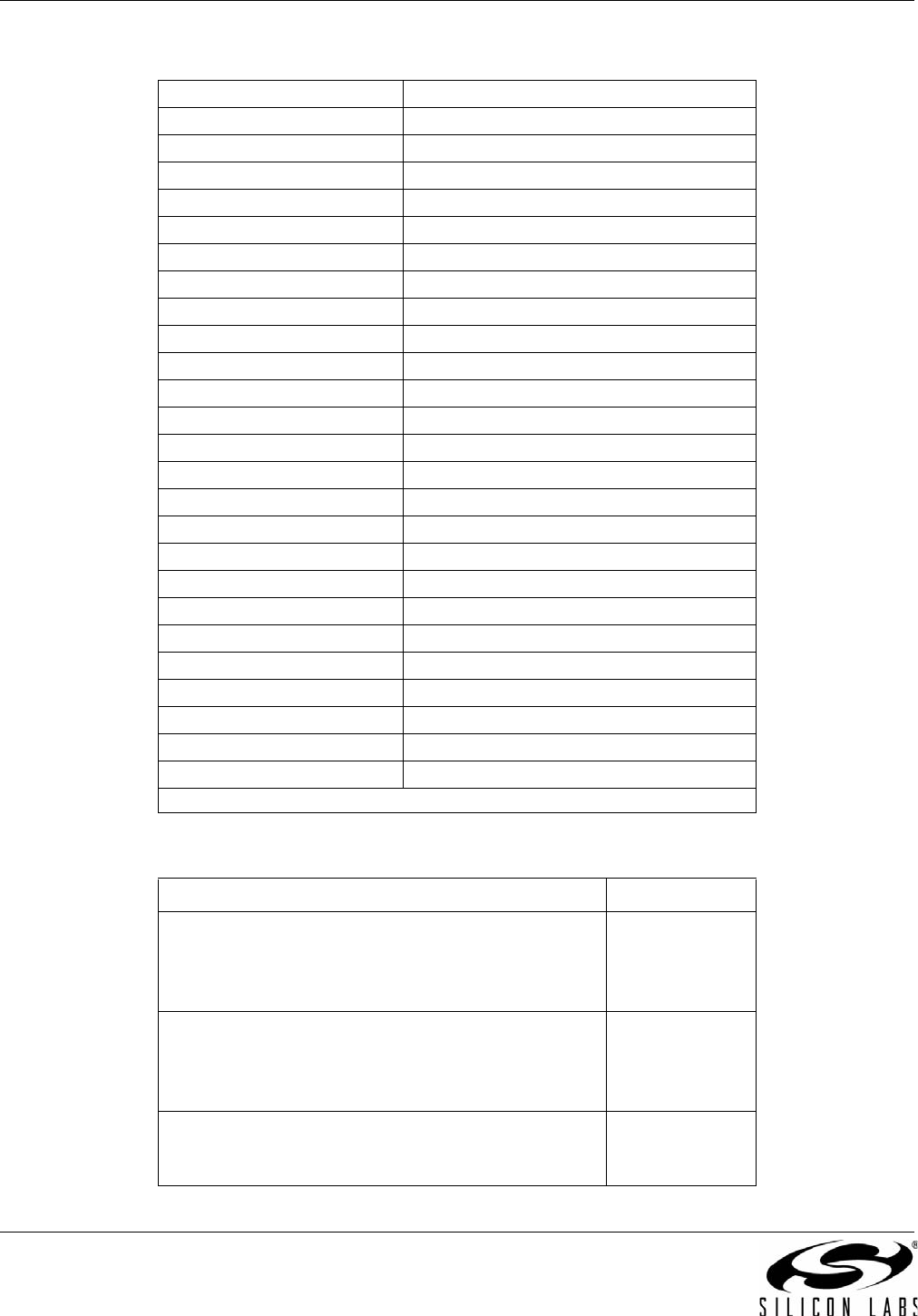
Table 149. Resistance across Components
Si3018/10 Resistance
FB1 < 1
FB2 < 1
RV1 > 20 M
R1 1.07 k
R2 150
R3 3.65 k
R4 2.49 k
R5 100 k
R6 100 k
R7 4.5 or 16 M
R8 4.5 or 16 M
R9 > 800 k
R10 536
R11 73
R12 < 1
R13 < 1
R15 < 1
R16 < 1
C1 > 20 M
C2 > 20 M
C3 > 3 M
C4 3.5 M or 9.7 M
C7 2 M or 5 M
C8 > 20 M
C9 > 20 M
Note: If two values are given, the resistance measured is dependent on polarity.
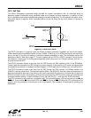
Table 150. Voltages across Components with Diode Checker
Component Voltage
Q1, Q3, Q4, Q5:
Base (red lead) to Emitter (black lead)
Base (red lead) to Collector (black lead)
(Verifies transistors are NPN)
0.6 V
0.6 V
Q2:
Emitter (red lead) to Base (black lead)
Collector (red lead) to Base (black lead)
(Verifies transistor is PNP)
0.6 V
0.6 V
Collector of Q2 (red lead)
to pin 1 of Si3018/10 (black lead)
If test fails, Z1 is reversed.
>1V