


16 Chapter 1 Overview
Chapter 1 Overview
– The output level of the luminance signal is different
from the specified value.
The above symptom is not a malfunction. This
condition will not affect images to be recorded on a
tape.The specified video signals are output from the S
VIDEO or VIDEO OUT jacks even in EE mode.
When you use this unit to input HDV signals from
the i.LINK jack and down-convert them to NTSC
(480i) or PAL (576i) signals, the specified video
signals are output.
• If you want to output video signals to the VIDEO, S
VIDEO, or COMPONENT OUT jack without text
data, select the [OTHERS] menu, [DISP OUTPUT],
then [LCD PANEL] (default setting). Or press the
DISPLAY/BATT INFO button on the unit, the
DATA CODE and SEARCH SELECT button on the
Remote Commander to clear the text data on the
monitor screen depending on the displayed items.
•During EE mode or recording, the subcarrier of the
color signal to be output from this unit is not
synchronized with the horizontal sync signal. The
color of the picture or the horizontal sync signal may
be distorted depending on the type of monitor
connected to the unit.
• The unit only can accept standard video signals.
If you input the types of video signals shown below,
recorded picture and sound may be distorted.
– Signals from some home game machines
–Blue background screen or gray background screen
from a consumer VCR
– Pictures played at a speed other than normal by a
VCR that does not have the TBC (Time Base
Corrector)
–Video signals in which the sync signals are
distorted
– Signals from a defective cassette (tape or recording
condition is bad) played by an analog VCR that
does not have TBC
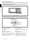
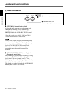
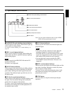
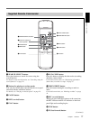
5 LANC jack
Use when controlling the tape transport operation of
the unit using a device that has a LANC
1)
jack.
Notes
• The LANC jack on the unit has only LANC-S
functions. The unit has no LANC-M functions. A
device that is set to LANC-S mode cannot be
connected to this unit. Either this, the unit or the other
device may not operate properly.
• If the device you connect to this unit has a SHUTTLE
A/B switching function and a LANC-M function, set
the device to the SHUTTLE A mode for processing
HDV signals and set it to the SHUTTLE B mode for
processing DVCAM/DV (SP mode) signals.
• The LANC connection transmits signals such as
control signals, time code, time counter data, and
status data.
• Jacks labeled CONTROL L have the same function
as LANC jacks.
•When using this unit as a player, set the LANC mode
on the recorder to M. A device that does not have an
M / S switching function cannot be used to control
this unit.
•You cannot use LANC to perform power control.
•You may have some difficulties when you edit using
an HDV formatted tape.
Refer to the “Notes” in “Editing (Connecting with a
Personal Computer)” on page 39.
6 HDV/DV jack (4-pin)
Used to input/output the digital signal that complies
with the i.LINK standard. Use when a device
connected to the unit has an i.LINK jack. If you
connect the unit and another device using
HDV/DV
jacks, you can minimize deterioration of picture
quality during recording, dubbing, or capturing still
pictures, all by means of digital signal processing. For
details, refer to the instruction manual of the external
device.
Note
This jack can accept only HDV/DV/DVCAM signals.
For details , see “About i.LINK” on page 72.
7 Battery terminal
For details on batteries, see “Preparing the Power Supply”
on page 22.
8 BATT RELEASE (battery release) button
Press this button to eject and remove a battery.
9 DC IN jack
Connects to an AC outlet using the supplied AC
adaptor and power cord.
........................................................................................................................................................................................................
1) LANC (Local Application Control bus system):
Bidirectional interface used to control a consumer VCR
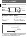
Location and Function of Parts