8 Chapter 1 Overview
Chapter 1 Overview
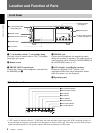
Location and Function of Parts
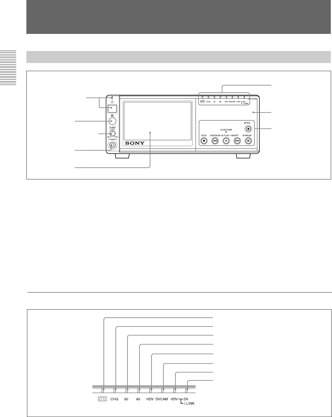
Front Panel
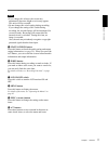
1 1 (on/standby) switch/ 1 (on/standby) lamp
Press this switch to turn the unit on. The 1 on/standby
lamp lights up in green.
2 Remote sensor
3 PHONE LEVEL control knob
Controls the volume of the headphones connected into
the PHONES jack 4.
4 PHONES jack
Connect stereo headphones for monitoring sounds
during the recording or playback. The audio signal you
want to monitor can be selected in [AUDIO MONI] on
the [AUDIO SET] menu. (p. 47)
5 LCD (Liquid Crystal Display) monitor
Displays the playback or EE
1)
pictures. Also,
superimposed time data, status information, menus,
audio level meters, etc. are displayed.
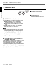
6 Operation panel
1 1 (on/standby) switch/
1 (on/standby) lamp
2 Remote sensor
3 PHONE LEVEL control knob
4 PHONES jack
5 LCD monitor
6 Operation panel
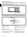
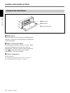
1 Indicator section
(see page 8)
2 Tape transport control
section
(see page 13)
........................................................................................................................................................................................................
1) “EE” stands for “Electric to Electric.” In EE mode, the video and audio signals input to the VCR’s recording circuitry do
not pass through any magnetic conversion circuits but output via electric circuits only. This mode is used to check the input
signals and adjust input levels. The pictures output in EE mode are referred to as EE pictures.
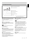
1 Indicator section
1 q (cassette) indicator
2 CHG (charge) indicator
3 50 indicator
4 60 indicator
5 HDV indicator
6 DVCAM indicator
7 HDV-i.LINK indicator
8 DV-i.LINK indicator


