


– 11 –
8
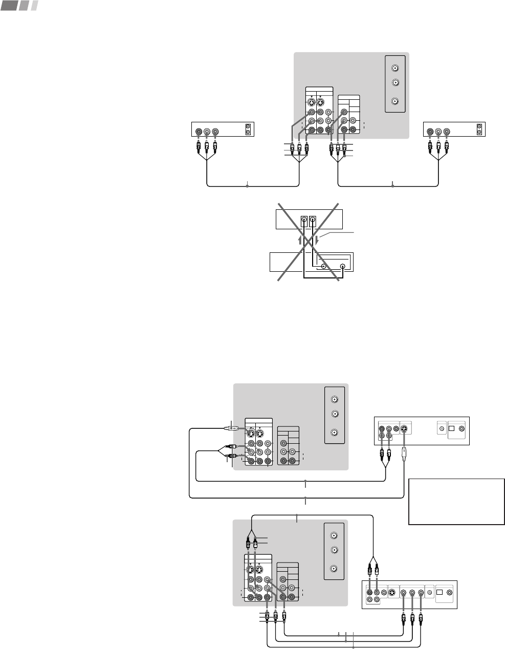
Installing and Connecting the Projection TV (continued)
S VIDEO
VIDEO
AUDIO
L
R
VIDEO
VHF/UHF
AUX
(MONO)
IN
VIDEO 1 VIDEO 3
OUT
MONITOR AUDIO
(VAR/FIX)
TO
CONVERTER
Y
P
B
PR
R
L
(MONO)
AUDIO
COMPONENT
AUDIO R AUDIO L VIDEO
LINE
OUT
OUT
IN
AUDIO R AUDIO L VIDEO
LINE
IN
OUT
IN
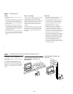
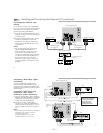
Disconnect all power sources before making any connections.
(Rear of projectionTV)
Indicates direction
of signal
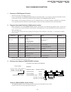
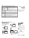
Connecting two VCRs for tape
editing
By connecting a second VCR to MONITOR
OUT, you can record a program being played
by the primary VCR to the second VCR or
perform tape editing and dubbing.
1 Connect the VCR intended for playback
using the connection instructions on page
6 of this manual.
2 Using an AUDIO/VIDEO cable, connect
AUDIO and VIDEO IN on the VCR
intended for recording to AUDIO and
VIDEO OUT of MONITOR OUT on the
projection TV.
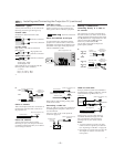
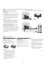
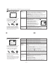
Notes:
• Do not change the input signal while
editing through MONITOR OUT.
• When connecting a single VCR to the
projection TV: if VCR LINE OUT is
connected to VIDEO IN on the projection
TV, do not connect MONITOR OUT on
the projection TV to the VCR LINE
INPUT (see right). Doing so will cause
program interference and other viewing
problems.
VIDEO
AUDIO-L
AUDIO-R
(Rear of projection TV)
VCR (for recording)
1
2
VMC-810S/820S
(not supplied)
VCR (for playback)
VMC-810S/820S
(not supplied)
LINE
OUT
IN
MONITOR
OUT
VIDEO IN
VCR
AUDIO-L
VIDEO
AUDIO-R
9
S VIDEO
VIDEO
AUDIO
L
R
VIDEO
VHF/UHF
AUX
(MONO)
IN
VIDEO 1 VIDEO 3
OUT
MONITOR AUDIO
(VAR/FIX)
TO
CONVERTER
Y
P
B
PR
R
L
(MONO)
AUDIO
COMPONENT
LINE OUT
S VIDEO OUT
S-LINK
DIGITAL OUT
R–AUDIO 1–L VIDEO
OPTICAL COAXIAL
S VIDEO
VIDEO
AUDIO
L
R
VIDEO
VHF/UHF
AUX
(MONO)
IN
VIDEO 1 VIDEO 3
OUT
MONITOR AUDIO
(VAR/FIX)
TO
CONVERTER
Y
P
B
PR
R
L
(MONO)
AUDIO
COMPONENT
LINE OUT
S VIDEO OUT
S-LINK
DIGITAL OUT
R–AUDIO 1–L VIDEO
OPTICAL COAXIAL
R-YY B-Y
COMPONENT VIDEO OUT
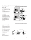
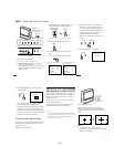
Disconnect all power sources before making any connections.
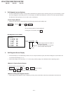
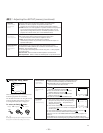
Connecting a DVD Player (Upper
illustration)
Using an AUDIO and S VIDEO cables,
connect AUDIO and S VIDEO IN on the
projection TV to AUDIO and S VIDEO OUT
on the DVD Player (White-AUDIO Left, Red-
AUDIO Right).
Connecting a DVD Player with
component video output
connectors (Lower illustration)
1 Using an AUDIO cable, connect AUDIO of
LINE OUT on the DVD Player to AUDIO of
VIDEO 3 IN on the projection TV (White-
AUDIO Left, Red-AUDIO Right).
2 Using three yellow VIDEO cables,
connect Y, P
B, and PR of COMPONENT
VIDEO OUT on the DVD Player to Y, P
B,
and P
R of VIDEO 3 IN on the projection
TV.
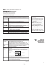
Note:
• Some DVD Player terminals may be labeled
differently. If so, connect as follows:
Connect Y (green) to Y.
Connect P
B (blue) to CB, Cb or B-Y.
Connect P
R (red) to CR, Cr or R-Y.
AUDIO-L
DVD
YC-15V/30V (not supplied)
(Rear of projection TV)
Audio/S video
outputs
AUDIO-R
S VIDEO
RK-74A (not supplied)
AUDIO-R
DVD
(Rear of
projection
TV)
Connect the DVD Player
directly to the projection TV.
Connecting the DVD Player
through other video
equipment will cause
unwanted picture noise.
PR
PB
Y
VMC-10HG
(not supplied)
RK-74A (not supplied)
AUDIO-L