


– 28 –
KP-43T70C/53SV70C/61SV70C
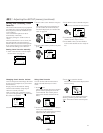
RM-Y906 RM-Y906 RM-Y906
3-1. SCREEN VOLTAGE ADJUSTMENT
(ROUGH ALIGNMENT)
1. Receive the Monoscope signal.
2. Set 50% BRIGHTNESS and minimum PICTURE.
3. Turn the red VR on the FOCUS block all the way to the left
and then gradually turn it to the right until the point where you
can see the retrace line.
4. Next gradually turn it to the left to the position where the
retrace line disappears.
10. Set VPNT 28 RON to “000”, 29 GON to “000” and 30 BON
to “001” to show only the blue color.
11. Adjust blue CRT lens just the same as green.
*: Every time you press 6, the test signal changes to
“crosshatch+video signal” - “dots+video signal” -
“crosshach(black)” - “dots(black)” - off.
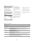
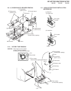
3-3. SCREEN (G2) ADJUSTMENT
1. Select VIDEO1 mode without signals.
2. Connect an oscilloscope to the TP701(KR), TP732(KG) and
TP761(KB) of CR board, CG board and CB board.
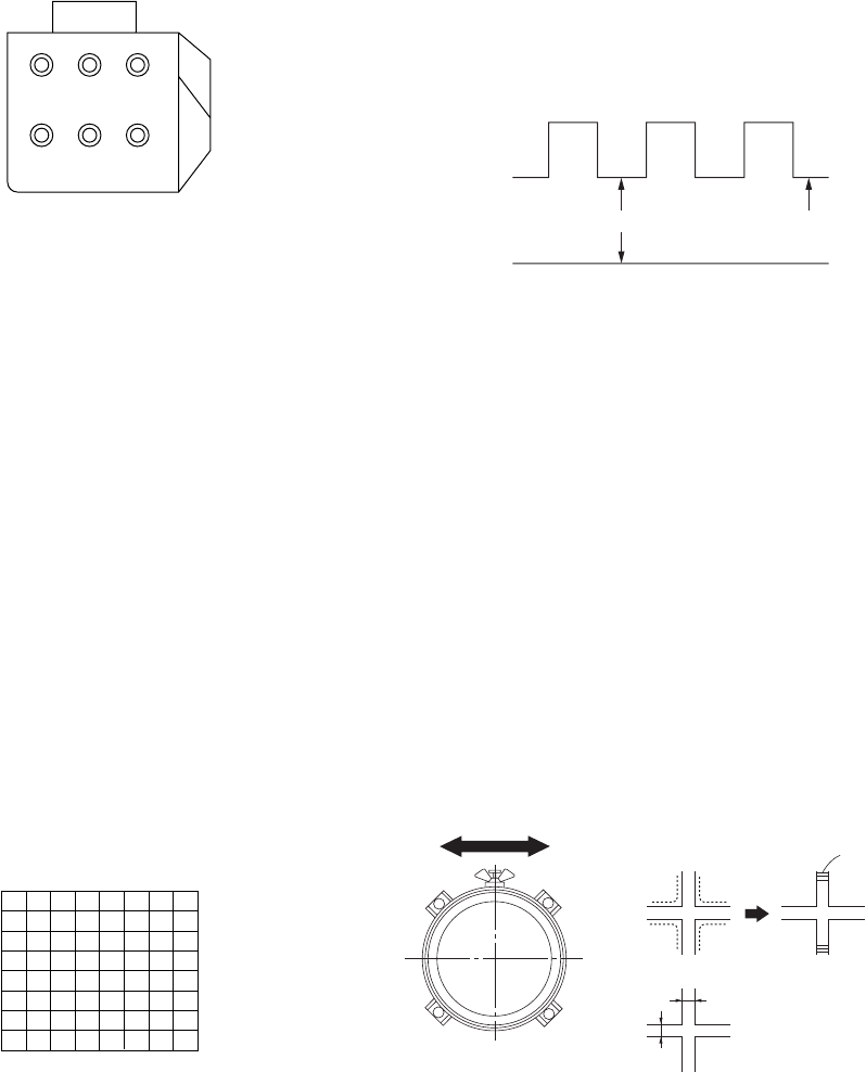
3. Adjust R, G and B screen voltage to 170 – 173V with screen
VR on the Focus block.
3-4. FOCUS VR ADJUSTMENT
1. Set to the service mode.
2. Change TV mode to the video input mode.
3. Set to PJE, and press 6 to display the test signal (crosshatch)
on the screen.
4. Set VPNT 28 RON to “000”, 29 GON to “001” and 30 BON
to “000” to show only the green color.
5. Turn the green VR on the focus block to adjust to the optimum
focus point with the test signal.
6. Set VPNT 28 RON to “001”, 29 GON to “000” and 30 BON
to “000” to show the red color.
7. Turn the red VR on the focus block to adjust to the optimum
focus point with the test signal.
8. Set VPNT 28 RON to “000”, 29 GON to “000” and 30 BON
to “001” to show the blue color.
9. Turn the blue VR on the focus block to adjust to the optimum
focus point with the test signal.
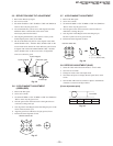
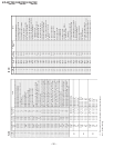
R G B
SCREEN
R G B
FOCUS
FOCUS block
Fig. 3-1
170 – 173V
GND
pedestal level
Fig. 3-3
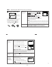
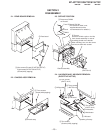
3-2. FOCUS LENS ADJUSTMENT
In this adjustment, use the remote commander in the
service mode.
For details of the usage of the service mode and the remote
commander, please refer the item 3-9. ELECTRICAL
ADJUSTMENT BY REMOTE COMMANDER.
1. Loosen the lens screw.
2. Set to the service mode.
3. Change TV mode to the video input mode.
4. Set to PJE, and press 6 to display the test signal (crosshatch)“
on the screen.
5. Set VPNT 28 RON to “000”, 29 GON to “001” and 30 BON
to “000” to show only the green color.
6. Turn the green lens to adjust to the optimum focus point with
the test signal.
7. Tighten the lens screw.
8. Set VPNT 28 RON to “001”, 29 GON to “000” and 30 BON
to “000” to show only the red color.
9. Adjust red CRT lens just the same as green.
SECTION 3
SET-UP ADJUSTMENTS
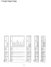
Fig. 3-5Fig. 3-4
A
B
Lens
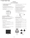
Minimize both A and B.
Center of crosshatch
Scanning line visible.
Fig. 3-2
Test signal