


– 29 –
KP-43T70C/53SV70C/61SV70C
RM-Y906 RM-Y906 RM-Y906
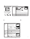
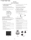
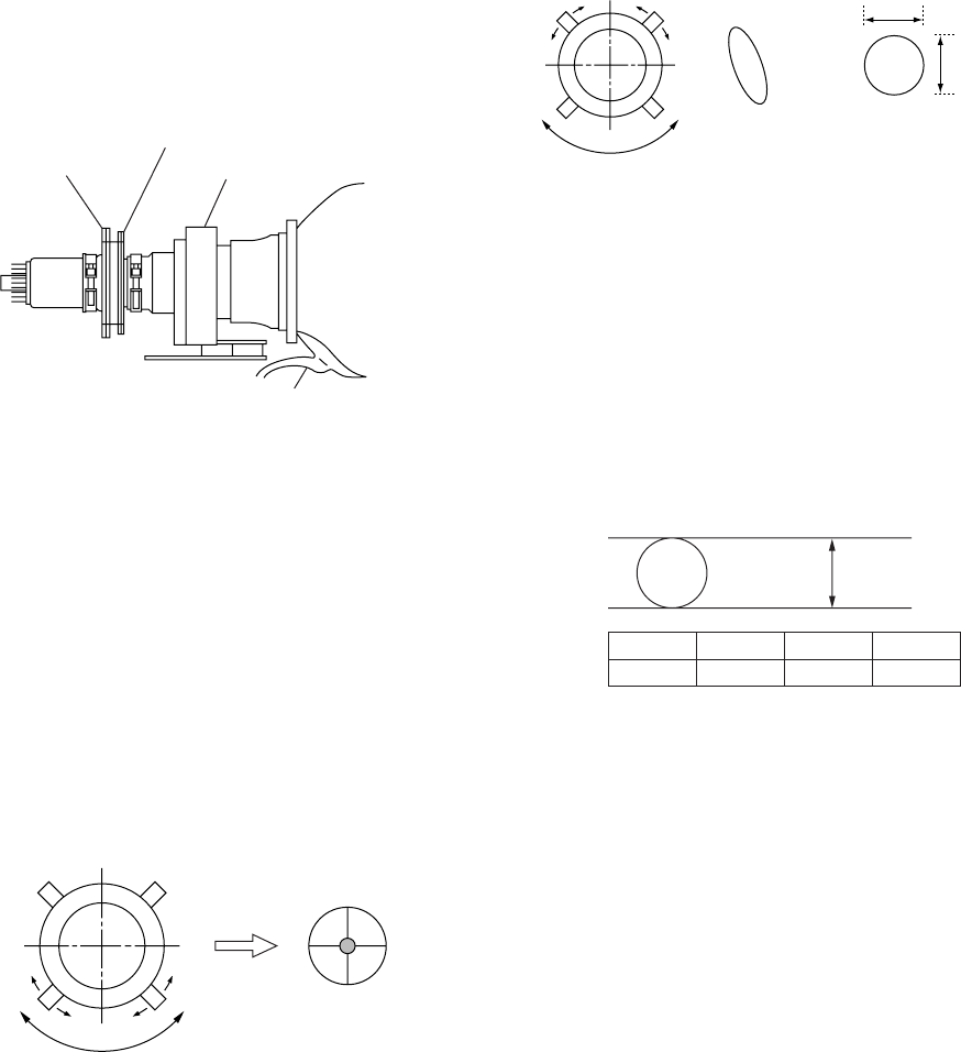
3-5. DEFLECTION YOKE TILT ADJUSTMENT
1. Receive the Monoscope signal.
2. Set in service mode.
3. Set VPNT 29 GON to “001” 28 RON to “000” and 30 BON to
“000” to show only the green color.
4. Loosen the deflection yoke set screw and align the tilt of the
Deflection Yoke so that the bars at the center of the
monoscope pattern are horizontal.
5. After aligning the deflection yoke, fasten it securely to the
funnel-shaped portion (neck) of the CRT.
6. The tilt of the deflection yoke for red is aligned in the mode
VPNT 28 RON “001”, 29 GON “000”, 30 BON “000” on the
service mode menu, and the tilt of the deflection yoke for biue
is aligned with in the mode VPNT 28 RON “000”, 29 GON
“000”, 30 BON “001” on the service menu, is aligned the
same as was done for green.
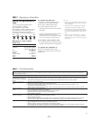
3-7. 4-POLE MAGNET ADJUSTMENT
1. Receive the Dot signal.
2. Set in service mode.
3. Set VPNT 29 GON to “001” 28 RON to “000” and 30 BON to
“000” to show only the green color.
4. Turn the green VR on the focus block to the left and set to
underfocus to enlarge the spot.
5. Now align the 4-Pole Magnet so that the enlarged spot
becomes a perfect circle for green and red.
6. Perform the same alignment for blue.
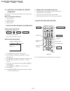
3-8. DEFOCUS ADJUSTMENT (BLUE)
1. Select the video menu and set the mode to “Vivid” mode.
2. Set to the service mode.
3. Change TV mode to the video input mode.
4. Set to PJE, and press 6 to display the test signal (dots) on the
screen.
5. Turn the blue VR on the focus block to adjust to the diameter
of the dots as shown in the figure below.
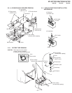
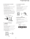
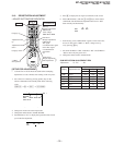
Fig. 3-6
2-pole magnet
4-pole magnet
Deflection yoke
Anode cap
3-6. 2-POLE MAGNET ADJUSTMENT
(GREEN,RED)
1. Receive the Dot signal.
2. Set in service mode.
3. Set VPNT 29 GON to “001” 28 RON to “000” and 30 BON to
“000” to show only the green color.
4. Turn the green VR on the focus block to the right and set to
overfocus to enlarge the spot.
5. Now align the 2-Pole Magnet so that the enlarged spot is in the
center of the Just Focus spot.
6. Align the green focus VR and set for just (precise) focus.
7. Perform the same alignment for red.
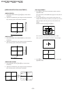
Use the center dot
Fig. 3-7
Fig. 3-8
[Focus adjustment point]
/
x
y
x : y = 1:1.5 (BIue)
x : y = 1:1 (Green, Red)
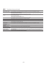
Use the center dot
Lmm Max
Inch
L
48"
7
53"
8
61"
9
Fig. 3-9