


– 41 –
KP-43T70C/53SV70C/61SV70C
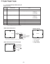
RM-Y906 RM-Y906 RM-Y906
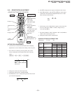
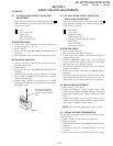
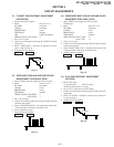
5-1. TV INPUT SUB CONTRAST ADJUSTMENT
(VPNT-SCON)
1. Receive the color-bar signal.
2. Mode : Personal 1 or 2.
PICTURE : maximum
COLOR : minimum
BRIGHTNESS : center
TRINITONE : medium
ABL : CN801 pin 4open
SERVICE DATA VPNT SCON : 7
3. Set to service mode.
4. Connect an oscilloscope between pin 7 of CN204 (A board)
and ground.
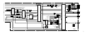
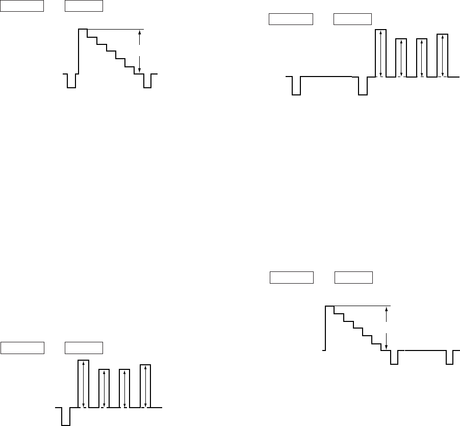
5. Select “ VPNT-SCON ”, and adjust so that the wave from
level is 1.80 ± 0.05Vp-p.
6. Write the data into memory.
MUTING n ENTER
White
1.80
±
0.05Vp-p
Black
Fig. 5-1
SECTION 5
CIRCUIT ADJUSTMENTS
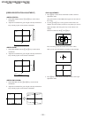
5-2. VIDEO INPUT SUB-HUE AND SUB-COLOR
ADJUSTMENT (VPNT-SHUE, SCOL)
1. Select VIDEO1 input and supply the color-bar signal.
2. Mode : Personal 1 or 2.
PICTURE : maximum
COLOR : center
BRIGHTNESS : center
TRINITONE : medium
SERVICE DATA VPNT-SHUE : 7
SERVICE DATA VPNT-SCOL : 7
3. Set to service mode.
4. Connect an oscilloscope between pin 5 of CN204 (A board)
connecter and ground.
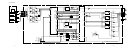
5. Select “ VPNT-SHUE, SCOL ”, and adjust them to have VB1
= VB4 and VB2 = VB3 in the waveform levels.
6. Increase SCOL by 2 steps.
7. Write the data into memory.
MUTING n ENTER
VB1 VB2 VB3 VB4
Fig. 5-2
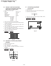
5-3.
COMPONENT INPUT SUB-HUE AND SUB-COLOR
ADJUSTMENT
(DAC-UVSH, UVSC)
1. Select VIDEO 4 and supply the color-bar signal.
VIDEO input
2. Mode : Personal 1 or 2.
PICTURE : maximum
COLOR : center
BRIGHTNESS : center
TRINITONE : medium
SERVICE DATA DAC UVSH : 31
SERVICE DATA DAC UVSC : 31
3. Set to service mode.
4. Connect an oscilloscope between pin 5 of CN204 (A board)
connecter and ground.
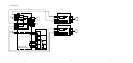
5. Select “ DAC-UVSH, UVSC ”, and adjust them to have VB1
= VB4 and VB2 = VB3 in the waveform levels.
6. Write the data into memory.
MUTING n ENTER
VB1 VB2 VB3 VB4
Fig. 5-3
5-4. P & P SUB CONTRAST ADJUSTMENT
(SC-SYDR)
1. Receive the signal.
TV terminal (sub) : color-bar signal
VIDEO terminal (main) : no signal
2. Set to service mode and set to P & P mode.
3. Connect an oscilloscope between pin 7 of CN204 (A board)
and ground.
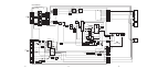
4. Select “ SC-SYDR ”, and adjust so that the wave from level
is 1.65 ± 0.05Vp-p.
5. Write the data into memory.
MUTING n ENTER
White
1.65
±
0.05Vp-p
Black
Fig. 5-4