


– 12 –
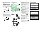
C521
C522
0
2
R620
C813
+
R802
R830
X801
R205
R
1
C811
C204
8
5
1
4
IC802
14914857
8
15115046
0
3215211
142141140
139138136
137135134
3336394244485154565758
3235384145475053555960
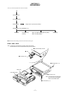
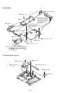
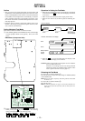
– MAIN Board (Component Side) –
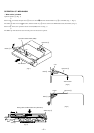
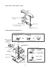
TAP801 (TEST)
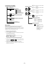
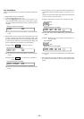
2 In the normal mode, turn on the HOLD switch on the set.
While pressing the x key on the set, press the following
remote commander keys in the following order:
N > t N > t . t . t N > t
. t N > t . t X t X
SECTION 4
TEST MODE
Operation in Setting the Test Mode
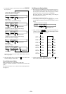
• When the test mode becomes active, first the display check mode
is selected. (Press the x key once, when the display check mode
is not active)
• Other mode can be selected from the display check mode.
• When the test mode is set, the LCD repeats the following dis-
play.
Set LCD display
Remote commander LCD display
• When the X key is pressed and hold down, the display at that
time is held so that display can be checked.
Caution: On the set having the microcomputer version 1.000, the
NV reset failure will occur.
Therefore, in executing the NV reset during electrical
adjustment, follow the troubleshooting method of NV
reset to perform the NV reset (see page 17).
Releasing the Test Mode
For test mode set with the method 1:
Turn off the power and open the solder bridge on TAP801 (TEST)
on the MAIN board.
Note: Remove the solders completely. Remaining could be shorted with
the chassis, etc.
For test mode set with the method 2:
Turn off the power.
Note: If electrical adjustment (see page 17) has not been finished com-
pletely, always start in the test mode. (The set cannot start in nor-
mal mode)
Outline
• This set provides the Overall adjustment mode that allows CD
and MO discs to be automatically adjusted when in the test mode.
In this overall adjustment mode, the disc is discriminate between
CD and MO, and each adjustment is automatically executed in
order. If a fault is found, the system displays its location. Also,
the manual mode allows each individual adjustment to be auto-
matically adjusted.
• Operation in the test mode is performed with the remote com-
mander. A key having no particular description in the text, indi-
cates a remote commander key.
Setting Method of Test Mode
There are two different methods to set the test mode:
1 Short TAP801 (TEST) on the MAIN board with a solder bridge
(connect pin y; of IC801 to the ground). Then, turn on the
power.
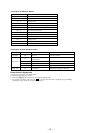
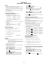
Microcomputer
version
display
All off
All lit
F1SHUF
REC
888
006 V1.000
u
888 100
All lit All off Microcomputer
version display